
Electric control lock

A technology of electric control lock and lock body, which is applied in the field of electric control lock, and can solve problems such as not being able to meet the needs of specific places, not being able to maintain the current state of the lock, and failure of the electromagnet.

Inactive Publication Date: 2012-05-02
JINAN ANBAO TECH
View PDF6 Cites 3 Cited by
  • Summary
  • Abstract
  • Description
  • Claims
  • Application Information

AI Technical Summary

Problems solved by technology

[0003] The purpose of the present invention is to solve the problem that the conventional electric control lock cannot maintain the current state of the lock when the power is off, the electromagnet fails after the power is off, and the lock is in a free state, which cannot be used in a specific place; Electric control lock with manual unlocking function; it has the advantages of centralized control / management of electric control locks through electrical signals (such as LAN or serial communication mode) under power-on conditions, and ensures that all controlled locks will remain in place when the power failure occurs. The current state (such as locked state) avoids the phenomenon of collective loss of control. At the same time, the lock has the characteristic of manual priority unlocking, that is, no matter whether the control circuit is valid or not, it can be manually controlled by the key.

Method used


Image

  • Electric control lock
  • Electric control lock
  • Electric control lock

Examples


Embodiment Construction

[0021] The present invention will be further described below in conjunction with the accompanying drawings and embodiments.

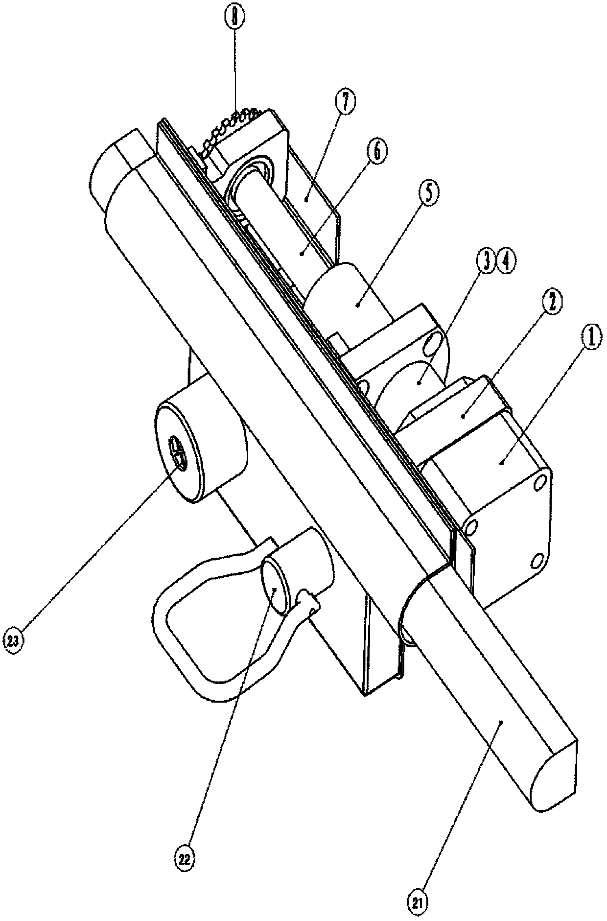
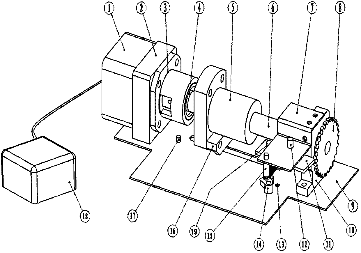
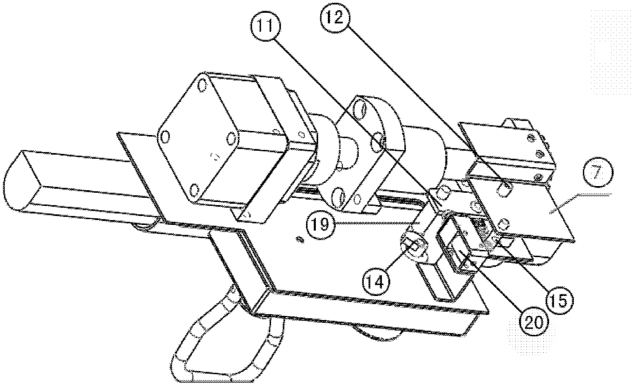
[0022] Electric lock, combined with figure 1 , figure 2 , image 3 , including base plate I, on which base plate I is provided with lock body 22, dead bolt / bolt 21, lock body 22 is provided with key hole 23, also includes base plate II 9, computer control unit 18, control actuator, control actuator and base plate II9 Connection, the base plate II 9 is connected with the base plate I, and the computer control unit 18 is connected with the control actuator through a circuit. Described control execution mechanism comprises stepper motor 1, motor seat 2, leading screw 6, bearing seat I 10, cam 14, cam sensor 13, motor seat 2, bearing seat I 10, cam sensor 13 are connected with base plate II 9 respectively , the stepper motor 1 is located on the motor base 2, one end of the lead screw 6 is connected with the stepper motor 1, the other end is connected wi...


PUM


Abstract

The invention discloses an electric control lock, which comprises a bottom plate I, a bottom plate II, a computer control unit and a controlling and executing mechanism, wherein a lock body and a lock tongue / bolt are arranged on the bottom plate I; a keyhole is arranged on the lock body; the controlling and executing mechanism is connected with the bottom plate II; the bottom plate II is connected with the bottom plate I; the computer control unit is connected with the controlling and executing mechanism by a circuit; the controlling and executing mechanism comprises a motor, a motor base, a guide screw, a bearing block I, a cam, a cam sensor, a clutch and a controlled electromagnet; the bearing block I is connected with a guide screw at one end of the clutch; a nut is arranged on the guide screw; the nut is connected with a shifting fork; the shifting fork is connected with the lock tongue / bolt; a bracket is arranged on the bearing block I; the bracket is provided with a rotating shaft and a tension spring component; the rotating shaft is connected with a lever on which a lever arm is arranged; the cam is matched with the lever arm; the controlled electromagnet is in contact withthe lever arm; and the keyhole is connected with the cam. The electric control lock has the advantage of centralized control; the phenomenon that the entire body is out of control is avoided; and theelectric control lock is particularly fit for working units, such as prisons / houses of detention, banks and the like for use.

Description

technical field [0001] The invention relates to the technical field of electric control locks, in particular to an electric control lock with the functions of power-off hold and manual priority. Background technique [0002] At present, the electric control locks currently available in the market can control the automatic opening and closing of the locks by electrical signals. It is in the "open" state (such as the bolt / bolt retracted, the door is open); because the bolt action of this type of electric control lock is mainly controlled by the electromagnet, the electromagnet will fail after the power is turned off, and the lock will be in a free state and cannot be opened It is used in some specific places, such as prisons / detention houses, banks and other financial institutions. In this case, it is required that the lock can be automatically controlled by electric signal when the power is turned on, and the lock control system will automatically lock / maintain the open / clos...

Claims


Application Information

Patent Timeline
IPC IPC(8): E05B47/06
Inventor 张欣赵博张平
Owner JINAN ANBAO TECH
Features
  • Generate Ideas
  • Intellectual Property
  • Life Sciences
  • Materials
  • Tech Scout
  • Unparalleled Data Quality
  • Higher Quality Content
  • 60% Fewer Hallucinations
Learn More