
High-speed turbine section for turbine drilling tool

A technology of turbo drilling tools and turbines, which is applied in the field of petroleum exploration and petroleum machinery and equipment, and can solve the problems of drastic changes in flow area, large pressure loss, and reduced efficiency of turbo drilling tools, and achieve smooth changes, reduce pressure loss, and improve stop The effect of thrust conditions

Active Publication Date: 2012-05-02
KINGDREAM PLC CO +1
View PDF5 Cites 6 Cited by
  • Summary
  • Abstract
  • Description
  • Claims
  • Application Information

AI Technical Summary

Problems solved by technology

The flow channel structure of the existing turbine section, due to the drastic change of the flow area, causes a large pressure loss and reduces the efficiency of the turbodrill

Method used


Image

  • High-speed turbine section for turbine drilling tool
  • High-speed turbine section for turbine drilling tool
  • High-speed turbine section for turbine drilling tool

Examples


Embodiment Construction

[0018] The present invention will be described in further detail below in conjunction with the accompanying drawings and embodiments.

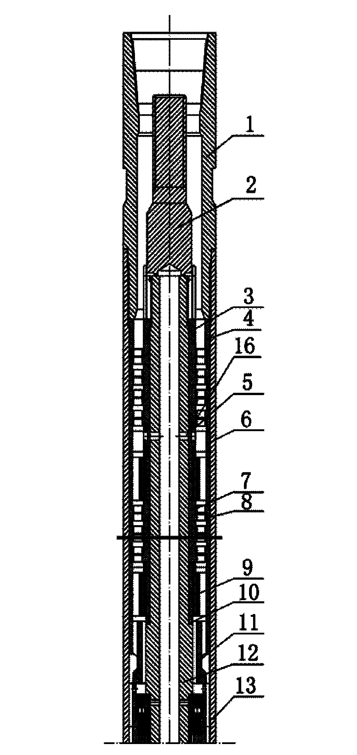
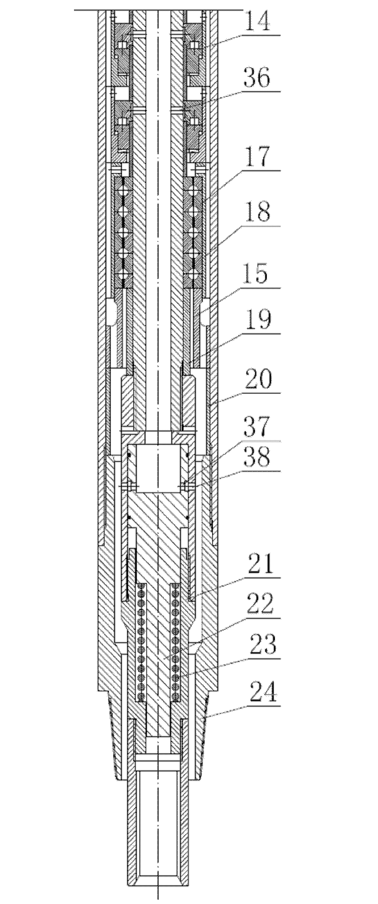
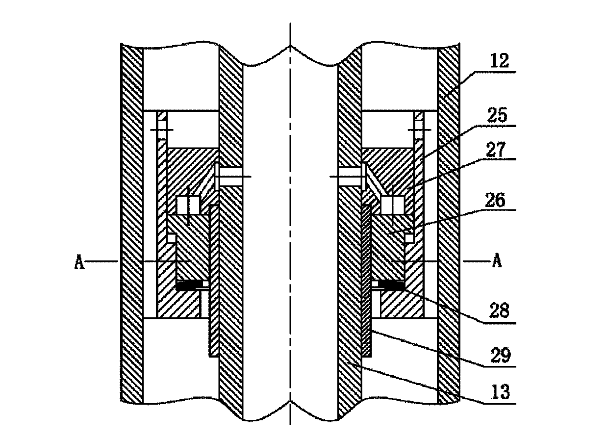
[0019] It includes a tubular casing 13, the two ends of the casing are respectively provided with an upper joint 1 with an internal taper thread and a lower joint 24 with an external taper thread, the casing is equipped with a turbine shaft 12, and the upper and lower ends of the turbine shaft are respectively threaded. The spline shaft 2 and the spline sleeve 21 are installed with a turbine assembly and a centering bearing 9 along the axial direction in the annular flow channel between the turbine shaft and the inner cavity of the housing. The turbine assembly is installed with 90 stages along the axial direction. The uppermost turbine assembly is equipped with 4 stages, and the uppermost 4-stage turbine assembly is used to filter mud impurities and prevent the upper radial through hole from being blocked. The centralizing bearings are install...


PUM


Abstract

The invention relates to a high-speed turbine section for a turbine drilling tool in the field of oil exploration, which is particularly suitable for a deep well and a directional well. The high-speed turbine section comprises a shell, wherein a turbine shell is mounted inside the shell in a penetrating manner; a spline shaft and a spline sleeve are respectively connected with the turbine shaft up and down; a turbine subassembly and a centering bearing are axially arranged in an annular runner between the turbine shaft and a shell inner cavity; and a bearing group is arranged below the turbine shaft. The high-speed turbine section is characterized in that a hydraulic balancing subassembly is mounted at the upper part of the bearing group below the turbine shaft; a center through hole which is through up and down is arranged on the turbine shaft; an upper radial through hole communicating with the center through hole is arranged above the turbine shaft so that the center through hole is communicated with the part above the shell inner cavity; and a lower radial through hole communicated with the center through hole is arranged corresponding to the hydraulic balancing subassembly, below the turbine shaft. In the invention, the runner of the turbine section is improved, the pressure consumption of the turbine drilling tool is reduced, and the whole machine efficiency of the turbine drilling tool is improved; meanwhile, the thrust load carrying conditions of the turbine shaft and the ball bearing group are improved, and the service life of the turbine drilling tool is prolonged.

Description

technical field [0001] The invention relates to the field of petroleum exploration, in particular to a high-speed turbodrilling tool turbine joint suitable for deep wells and directional wells, and belongs to the technical field of petroleum machinery and equipment. Background technique [0002] Turbodrilling tools used in fields such as oil exploration and production use the kinetic energy of drilling fluid to convert into mechanical energy to drive the drill bit to rotate and break rock. Due to the low level of early drilling equipment, the pressure drop of turbo drilling tools is generally required to be small. With the development of PDC bit technology, high-speed turbo matching bit becomes possible. In order to improve the output performance of the turbine, it is necessary to increase the displacement of the turbine, thereby increasing the mechanical energy of the drilling fluid. With the increasing pump pressure provided by the drilling pump and the application of hi...

Claims


Application Information

Patent Timeline
Patent Type & Authority Applications(China)
IPC IPC(8): E21B12/00E21B4/00
Inventor 田红平冯进周思柱叶道辉章靖张小俊
Owner KINGDREAM PLC CO
Learn More