Speed changing magnetic pump

A magnetic pump and magnetic transmission technology, applied in the field of transmission, can solve the problems of not being able to cut off the transmission relationship, damage the prime mover, damage the transmission, etc., and achieve the effects of avoiding electromagnetic interference, small energy loss, and long life

Inactive Publication Date: 2012-05-02
SHANGHAI DIANJI UNIV
View PDF2 Cites 89 Cited by
  • Summary
  • Abstract
  • Description
  • Claims
  • Application Information

AI Technical Summary

Problems solved by technology

However, the mechanical gear transmission has mechanical wear, vibration noise, needs lubrication, and cannot cut off the transmission relationship when overloaded, which will damage the transmission or damage the prime mover
And motor frequency conversion speed regulation will produce electromagnetic interference

Method used


Image

  • Speed changing magnetic pump
  • Speed changing magnetic pump
  • Speed changing magnetic pump

Examples


Embodiment Construction

[0020] The following describes the specific implementation of the variable speed magnetic pump of the present invention with reference to the accompanying drawings.

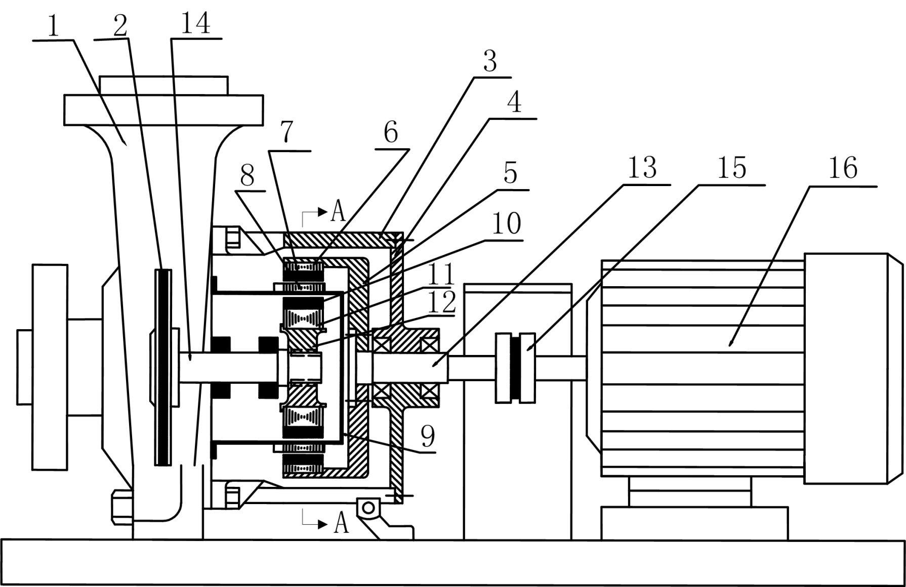
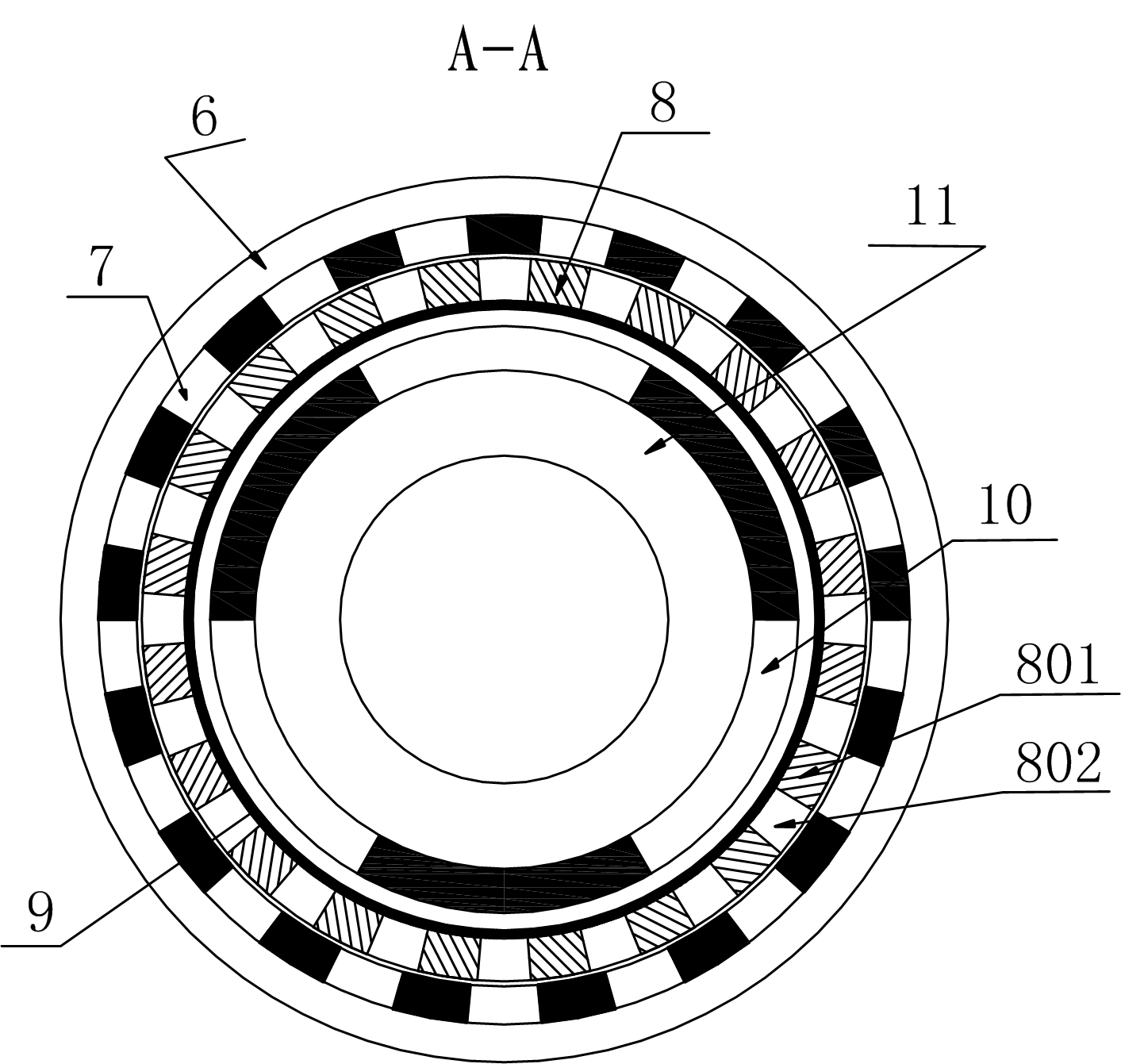
[0021] See attached figure 1 and 2 , a variable speed magnetic pump, including a pump body 1, a drive motor 16, and a variable speed magnetic transmission device arranged in the inner cavity of the housing 3; ring 8 ; the inner magnetic rotor includes an inner magnetic rotor magnet ring 10 and an inner magnetic rotor core 11 , and the outer magnetic rotor includes an outer magnetic rotor core 6 and an outer magnetic rotor magnet ring 7 .

[0022] The drive motor 16 drives the outer magnetic rotor to rotate through the coupling 15 and the input shaft 13 , and the input shaft 13 is arranged on a bearing inside the end cover 4 .

[0023] One outer magnetic rotor core 6 is arranged inside the cup-shaped sleeve 5 in the inner cavity of the housing 3, and the inner wall of the outer magnetic rotor iron core 6 is even...


PUM


Abstract

The invention provides a speed changing magnetic pump, which comprises a pump body, a speed changing magnetic transmission device installed in a casing cavity and a driving motor. The speed changing magnetic transmission device comprises an inner magnetic rotor, an outer magnetic rotor, an isolation sleeve and a magnetic field adjusting ring. The inner magnetic rotor comprises an inner magnetic rotor magnet ring and an inner magnetic rotor magnet core, the outer magnetic rotor comprises an outer magnetic rotor magnet core and an outer magnetic rotor magnet ring which forms an annular cavity with the inner magnetic rotor magnet ring, and the isolation sleeve fixedly connected with a pump body is arranged in the annular cavity. The magnetic field adjusting ring fixedly installed on the isolation sleeve is an annular body formed by connecting a plurality of magnet core blocks and a plurality of epoxy blocks at intervals and used for adjusting magnetic fields of the inner magnetic rotor and the outer magnetic rotor to enable the rotating speed of an output rotating shaft connected to an impeller in a pump body to be different from the rotating speed of an input rotating shaft connected to the driving motor.

Description

technical field [0001] The invention relates to the field of transmission technology, in particular to a variable-speed magnetic pump capable of adjusting the rotational speeds of an input shaft on a drive motor and an output shaft connected to a pump body. Background technique [0002] The magnetic pump consists of three parts: drive motor, magnetic drive, and pump body. The key component, the magnetic drive, consists of an outer magnetic rotor, an inner magnetic rotor and a non-magnetic isolation sleeve. When the drive motor drives the outer magnetic rotor to rotate, the magnetic field can penetrate the air gap and non-magnetic substances, and drive the inner magnetic rotor connected to the impeller on the pump shaft in the pump body to rotate synchronously, and the inner magnetic rotor drives the pump shaft to rotate, so that the impeller rotor Turn work. Generally, the inner and outer magnetic rotors have the same number of pole pairs, and the speed driven by the drivi...

Claims


Application Information

Patent Timeline
Patent Type & Authority Applications(China)
IPC IPC(8): F04D13/06H02K49/00H02K51/00
Inventor 杜世勤刘军
Owner SHANGHAI DIANJI UNIV
Why Eureka
Try Eureka