Terminal device

A terminal unit and terminal technology, applied in the direction of electrical components, contact parts, coupling devices, etc., can solve the problem that the movement track of the unlocking handle is difficult to become stable, and achieve the effect of reliable release

Inactive Publication Date: 2012-05-02
PANASONIC INTELLECTUAL PROPERTY MANAGEMENT CO LTD
View PDF5 Cites 14 Cited by
  • Summary
  • Abstract
  • Description
  • Claims
  • Application Information

AI Technical Summary

Problems solved by technology

This causes the problem that the movement trajectory of the unlocking handle is difficult to become stable

Method used


Image

  • Terminal device
  • Terminal device
  • Terminal device

Examples


no. 1 example

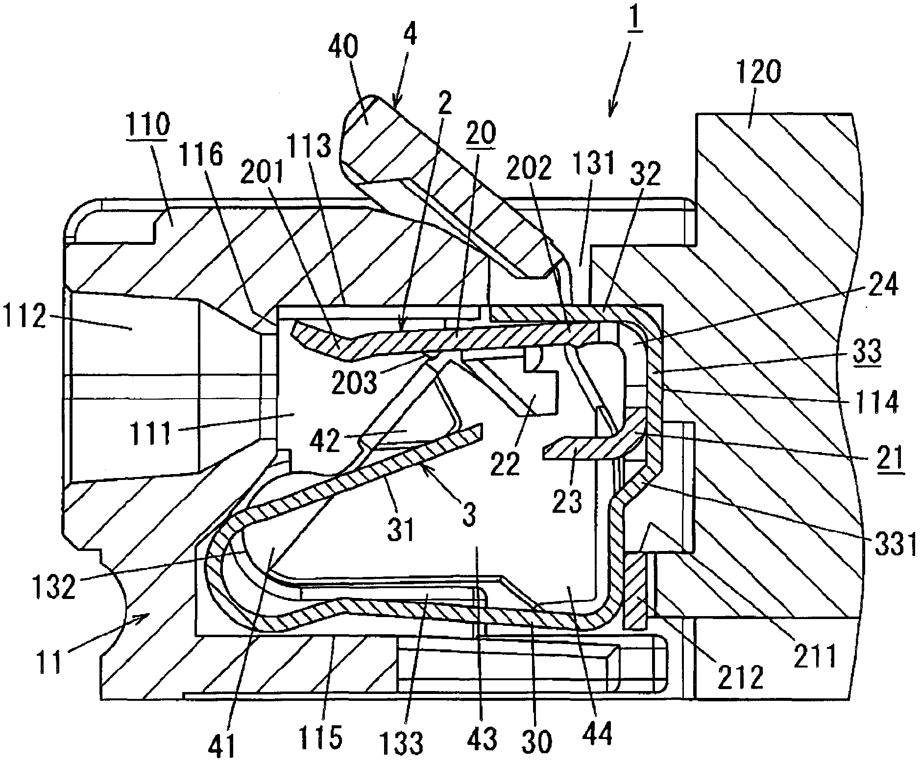
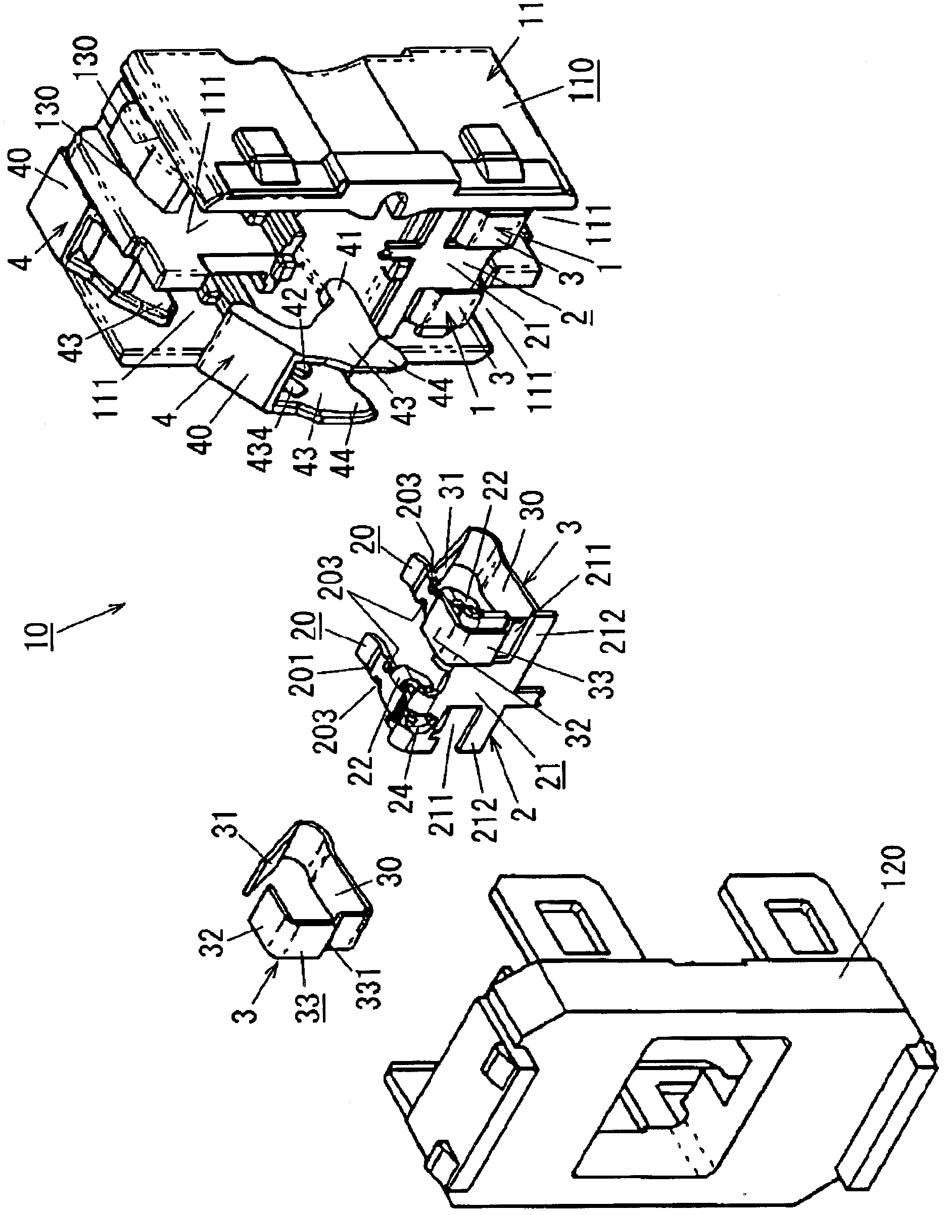
[0033] The terminal unit according to the present embodiment is equipped with, for example, figure 2 Embedded wiring device 10 is shown. In the following description, the up-down direction, front-back direction, and left-right direction are defined according to the state in which the wiring device 10 is attached to the wall (in figure 2 , the up-down direction is vertical, the lower-left side is forward and the upper-left side is left). However, these definitions are not intended to limit the orientation in which the terminal unit may be used.

[0034] Such as figure 2 The illustrated wiring device 10 includes a device housing 11 made of synthetic resin. The device case 11 includes a rectangular box-shaped body 110 having a front opening, and a cover 120 combined with the body 110 to cover the opening of the body 110 .

[0035] A pair of storage chambers 111 arranged side by side in a lateral direction (left-right direction) are formed in each longitudinal (vertical) op...

no. 2 example

[0087] The terminal unit 1 of the present embodiment is fitted to an outlet as a wiring device. The terminal unit 1 of this embodiment differs from the terminal unit 1 of the first embodiment in that Figure 8 Protrusions 213 are formed in the clamping tab 21 of the illustrated end plate 2 .

[0088]The protrusion 213 is formed on a clamping surface 214 which is one thickness direction surface (front surface) of the clamping piece 21 . The protrusions 213 are arranged between the insertion grooves 211 of the clamping pieces 21, and have a circular shape as seen in plan view. The protrusion 213 protrudes forward from the clamping surface 214 . The protruding dimension of the protrusion 213 is set to be greater than the thickness of the connecting piece 33 of the lock spring 3 . In other words, the height of the protrusion 213 from the clamping surface 214 is set to be greater than the height of the connecting piece 33 of the lock spring 3 from the clamping surface 214 .

[...


PUM


Abstract

The invention provides a terminal device used together with the housing of equipment provided with an insertion hole, which comprises a locking spring formed by leaf springs and configured to lock a wire inserting into the insertion hole of the housing of equipment; and an unlocking handle. The unlocking handle used for releasing the locking of the wire through the locking spring comprises a fulcrum shaft and an actuating part. The fulcrum shaft is supported on the housing at one side opposite to the locking spring. The actuating part is arranged to be rotated around the fulcrum shaft when the unlocking handle is in operation. Meanwhile, the actuating part pushes the transverse end portion of the locking spring so as to unlock the wire.

Description

technical field [0001] The present invention relates to a terminal unit for simultaneously electrically connecting and mechanically clamping electric wires inserted from an insertion hole of a device housing, and a wiring device including the terminal unit. Background technique [0002] To simplify the work of connecting wires in wiring devices such as receptacles and switches, quick-connect terminal units are routinely available which simultaneously electrically connect and mechanically clamp the wires inserted through the insertion holes in the housing of the device , to be able to connect wires without using screws. [0003] As an example of this type of terminal unit, there is known a terminal unit including a lock spring for locking an electric wire inserted through an insertion hole of the device housing and preventing When a tool such as a screwdriver is manipulated through a manipulation hole defined in the device casing, the unlocking button is used to unlock the w...

Claims


Application Information

Patent Timeline
Patent Type & Authority Applications(China)
IPC IPC(8): H01R13/639H01R13/516H01R13/24
CPCH01R4/48365
Inventor 奥野裕寿柴田究藤原洋子氏原秀哲野村秀和坂地高周西垣俊司辰巳隆登志
Owner PANASONIC INTELLECTUAL PROPERTY MANAGEMENT CO LTD
Why Eureka
Try Eureka