
Control circuit of double-light-source intelligent control type illumination lamp

A technology for intelligent control and lighting fixtures, applied in energy-saving control technology, electric lamp circuit arrangement, light source, etc., can solve problems such as unfavorable promotion, difficulty in implementation, high cost, etc., and achieve the effect of convenient use, favorable promotion and low cost

Active Publication Date: 2012-05-02
KENNEDE ELECTRIONICS MFG CO LTD
View PDF5 Cites 2 Cited by
  • Summary
  • Abstract
  • Description
  • Claims
  • Application Information

AI Technical Summary

Problems solved by technology

However, this kind of emergency lighting bulb cannot judge the switch state of the wall switch, or it needs to make certain modifications to the circuit or wall switch of the user's wall to realize the use of the wall switch to control the switch of the emergency light bulb. Difficult, increases implementation cost, is not conducive to promotion
In addition, this kind of light bulb can only use a single light source. If you use an AC energy-saving lamp, the brightness is guaranteed, but the power consumption is too large, which does not meet the emergency lighting time requirements or requires a higher backup power supply; if you use an LED lamp, the power consumption is reduced. Reduced, but the brightness is insufficient or the cost is relatively high during normal lighting

Method used


Image

  • Control circuit of double-light-source intelligent control type illumination lamp
  • Control circuit of double-light-source intelligent control type illumination lamp
  • Control circuit of double-light-source intelligent control type illumination lamp

Examples


Embodiment Construction

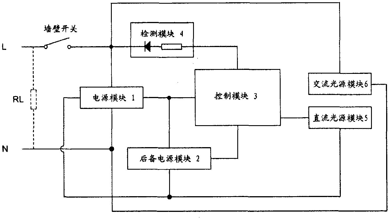
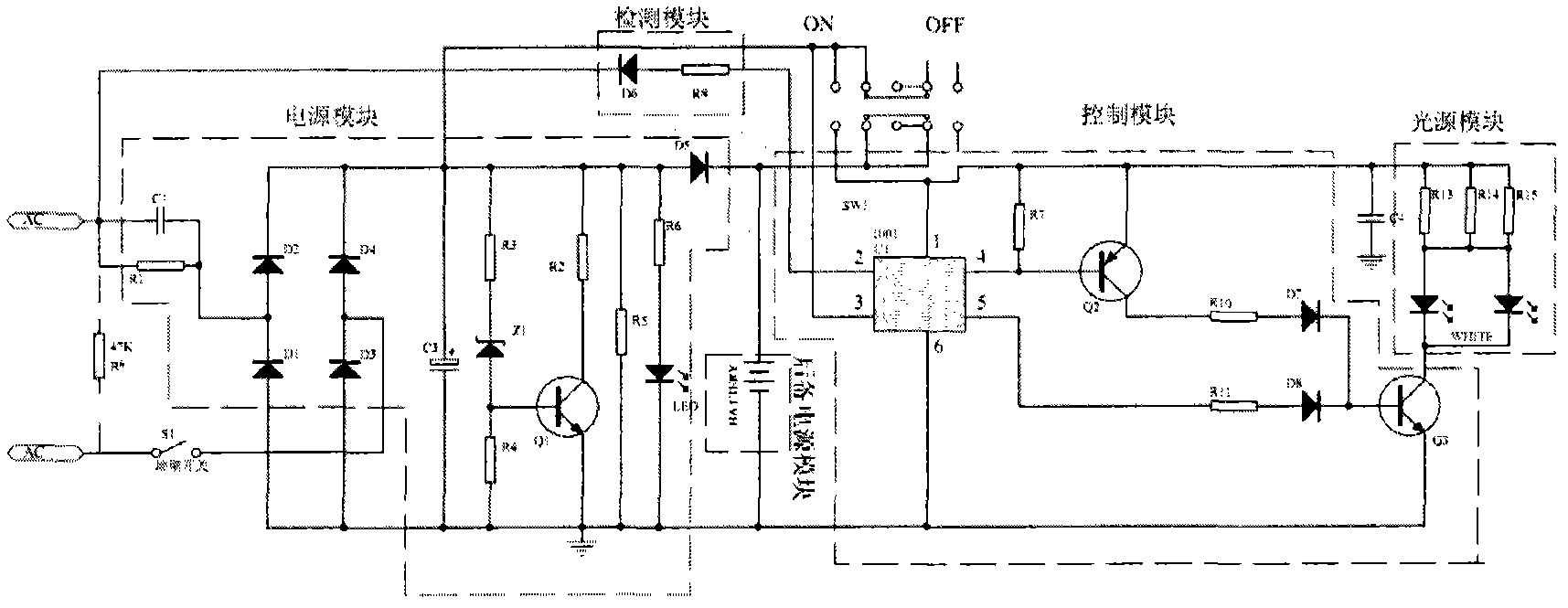
[0011] Such as figure 1 As shown, a dual light source intelligent control type lighting control circuit includes a power supply module 1, a backup power supply module 2, a control module 3, a wall switch detection module 4, a DC light source module 5 and an AC light source module 6, wherein the power supply module 1 The input end is connected with the grid behind the wall switch, the output end is connected with the input end of the backup power supply module 2 and the control module 3, the control module 3 is also connected with the output end of the backup power supply module 2, and the wall switch detection module 4 is connected in series Between the control module 3 and the power grid behind the wall switch, one end of the DC light source module 5 is connected to the backup power module 2, and the other end is connected to the output end of the control module 3, and the AC light source module 6 is directly connected to the power grid behind the wall switch.

[0012] Wherei...


PUM


Abstract

The invention discloses a control circuit of a double-light-source intelligent control type illumination lamp. The control circuit comprises a power supply module, a backup power supply module, a control module, a wall switch detection module, a direct-current light source module and an alternating-current light source module, wherein the wall switch detection module is serially connected between the control module and a power net behind the wall switch; the wall switch detection module, the control module, the power supply module, the backup power supply module, the wall switch and the power net form a wall switch detection loop; one end of the direct-current light source module is connected with the backup power supply module and the other end of the direct-current light source module is connected with the output end of the control module; and the alternating-current light source module is connected with the power net behind the wall switch directly. According to the invention, the on / off of an emergency lamp can be controlled by the existing wall switch remotely; in normal illumination, a common alternating-current light source is used; and while in emergency illumination, a low-voltage energy-saving direct-current light source is used, so that the existing wiring of a user needs no change, and the control circuit has low maintenance cost, convenience in application and easiness in popularization.

Description

technical field [0001] The invention relates to an emergency lighting fixture, in particular to a dual light source intelligent control type lighting fixture control circuit. Background technique [0002] Emergency lights are lamps that use their own power supply to provide temporary lighting when the normal lighting system fails to provide normal lighting due to power supply failure. Except for the portable type, this kind of emergency lighting usually requires additional wiring and installation, and the switch on and off of the lighting is controlled by the built-in switch when needed, which is inconvenient to use. Now there is a kind of emergency bulb integrated with control circuit and backup power supply in the market, which can directly use the existing lamp holder, provide daily lighting function when the power supply is normal, and provide emergency lighting service when the power is cut off, which is convenient for users. However, this kind of emergency lighting bu...

Claims


Application Information

Patent Timeline
Patent Type & Authority Applications(China)
IPC IPC(8): H05B37/02
CPCY02B20/48Y02B20/40
Inventor 田畴
Owner KENNEDE ELECTRIONICS MFG CO LTD
Learn More