Hydrocarbon oil catalytic cracking method and equipment
A technology for catalytic cracking and hydrocarbon oil, applied in the fields of hydrocarbon oil catalytic cracking and hydrocarbon oil catalytic cracking equipment, can solve the problems of large gas-solid back-mixing, decreased catalyst activity, and increased gasoline olefin content, etc.
- Summary
- Abstract
- Description
- Claims
- Application Information
AI Technical Summary
Problems solved by technology
Method used
Image
Examples
Embodiment approach
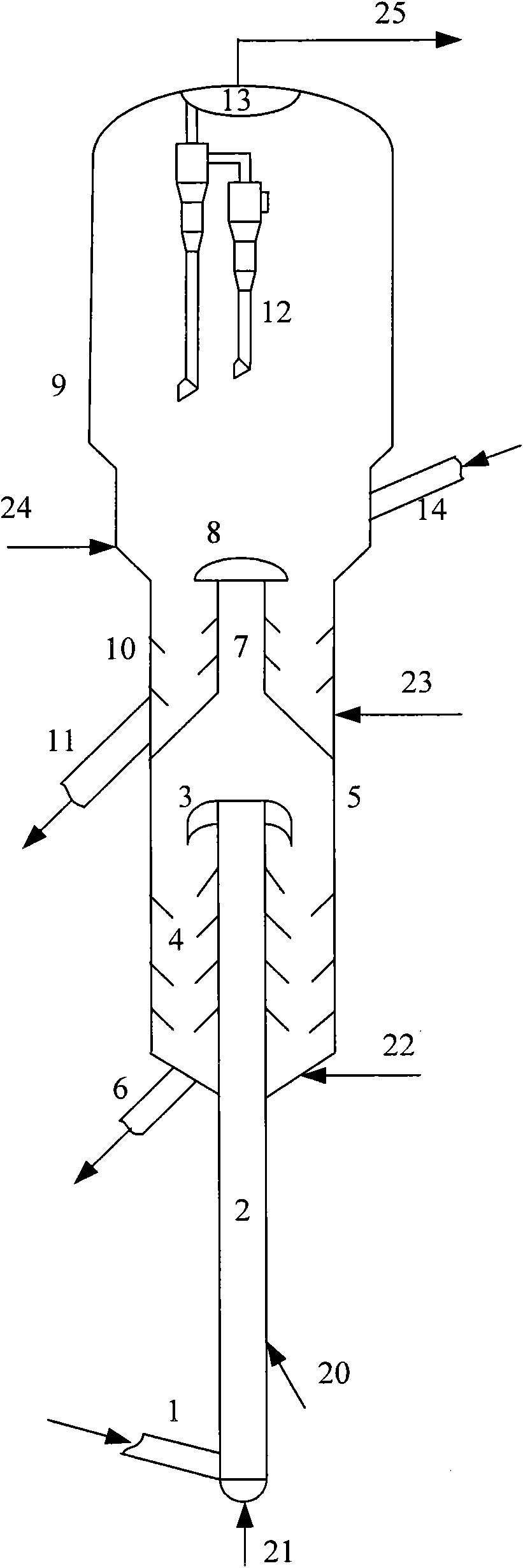
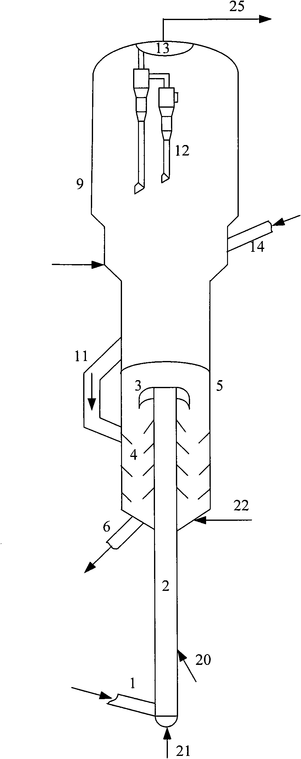
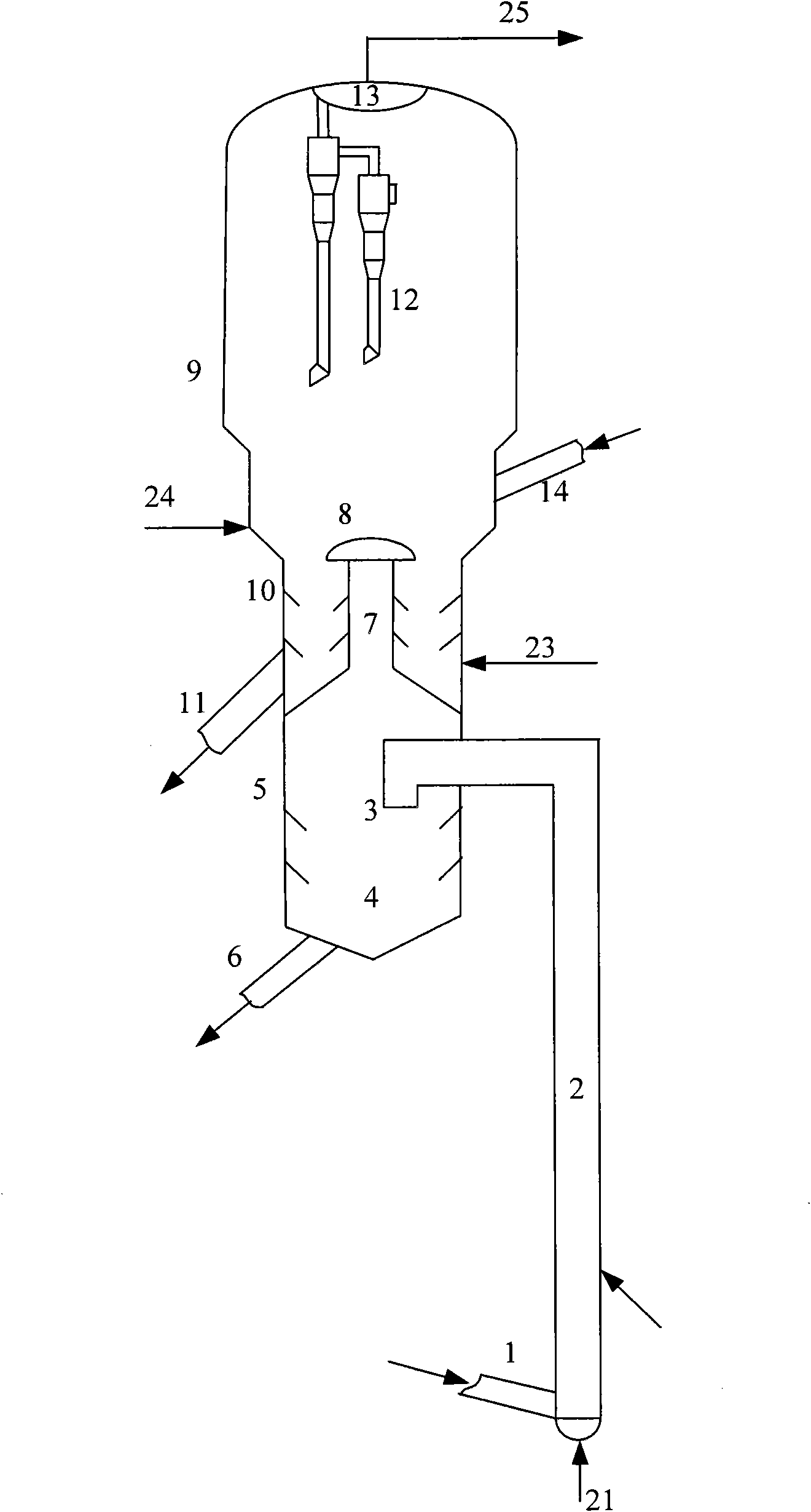
[0048] According to one embodiment of the present invention, preferably, as figure 1 As shown, the hydrocarbon oil catalytic cracking equipment provided by the present invention also includes the second stripping section 10 positioned at the lower part of the fluidized bed reactor 9, used for stripping the reacted catalyst in the fluidized bed reactor 9, the second stripping section 10 The lower part of the section 10 is also communicated with a second spent agent output pipe 11 and a second stripping medium input pipe 23 . The second spent agent output pipe 11 may communicate with the first stripping section 4, or directly communicate with the catalyst regenerator.
[0049] According to the present invention, each of the first stripping section 4 and the second stripping section 10 is preferably provided with a stripping baffle. The arrangement of the stripping baffle is well known to those skilled in the art, and will not be repeated here.
[0050] Further preferably, a ga...
Embodiment 1-3
[0064] This example is used to illustrate the hydrocarbon oil catalytic cracking equipment and hydrocarbon oil catalytic cracking method provided by the present invention.
[0065] use figure 1 The hydrocarbon oil catalytic cracking equipment shown has a processing capacity of 2 kg / h, the height ratio of the riser reactor 2 and the fluidized bed reactor 9 is 2:1, and the diameter ratio is 1:5. The raw material oil is first reacted in the riser reactor 2, and then the oil gas after the deactivated catalyst is separated by the inertial separator 3 is introduced into the fluidized bed reactor 9 to continue the reaction, and the oil gas and catalyst mixture after the reaction are subjected to oil separation , the catalyst after the oil agent separation and the inertial separator 3 separate the deactivated catalyst to obtain the raw catalyst after stripping, and the stripping medium is water vapor at a temperature of 250°C. The catalyst used in riser reactor 2 and fluidized bed re...
Embodiment 4-6
[0071] This example is used to illustrate the hydrocarbon oil catalytic cracking equipment and hydrocarbon oil catalytic cracking method provided by the present invention.
[0072] Carry out the catalytic cracking of hydrocarbon oil according to the method for embodiment 1, difference is that feedstock oil is feedstock B, the catalyst that riser reactor 2 adopts is MLC-500 balance agent, the catalyst that fluidized bed reactor 9 adopts is MMC -2 Catalyst. This embodiment is for the purpose of producing more low-carbon olefins (gasoline+diesel oil), the temperature of the fluidized bed reactor 9 is higher than the temperature of the riser reactor 2, and the reaction conditions of the fluidized bed reactor 9 are higher than that of the riser reactor 2. More severe, reaction conditions and results are shown in Table 4.
PUM
 Abstract
Description
Claims
Application Information
 - R&D
- Intellectual Property
- Life Sciences
- Materials
- Tech Scout
- Unparalleled Data Quality
- Higher Quality Content
- 60% Fewer Hallucinations
Browse by: Latest US Patents, China's latest patents, Technical Efficacy Thesaurus, Application Domain, Technology Topic, Popular Technical Reports.
© 2025 PatSnap. All rights reserved.Legal|Privacy policy|Modern Slavery Act Transparency Statement|Sitemap|About US| Contact US: help@patsnap.com


