Catalytic cracking method and equipment for hydrocarbon oil

A catalytic cracking and hydrocarbon oil technology, which is applied in the field of hydrocarbon oil catalytic cracking and hydrocarbon oil catalytic cracking equipment, can solve the problems of weakened catalytic effect, increased olefin content in gasoline, and increased thermal cracking reactions, so as to increase the ratio of catalyst to oil and reduce the contact The effect of temperature

Inactive Publication Date: 2012-05-16
CHINA PETROLEUM & CHEM CORP +1
View PDF12 Cites 12 Cited by
  • Summary
  • Abstract
  • Description
  • Claims
  • Application Information

AI Technical Summary

Problems solved by technology

However, due to the gas-solid co-current flowing against the gravity field, there is a large axial and radial flow inhomogeneity in the riser, large gas-solid backmixing, uneven residence time distribution, etc., and the coke generated during the reaction is deposited on the catalyst. On the surface and active center, the activity of the catalyst drops sharply
Studies have shown that the current catalyst activity at the outlet of the riser is only about 1 / 3 of the initial activity, and the reaction takes about 1 second, and the catalyst activity drops by about 50%.
In this way, in the second half of the riser reactor, the activity of the catalyst drops sharply, the catalytic effect is greatly weakened, the thermal cracking reaction increases, more dry gas is produced and the olefin content of gasoline is increased.

Method used


Image

  • Catalytic cracking method and equipment for hydrocarbon oil
  • Catalytic cracking method and equipment for hydrocarbon oil
  • Catalytic cracking method and equipment for hydrocarbon oil

Examples


Embodiment approach

[0036] According to one embodiment of the present invention, the method also includes adding hydrocarbon oil to the second reactor, and making the added hydrocarbon oil and the oil gas after the separation of the first oil agent and the newly added second cracking catalyst carry out the described In the second contact reaction, the hydrocarbon oil is one or more of the hydrocarbon oil feedstock, dry gas, liquefied gas, light hydrocarbons, gasoline, diesel oil, recycled oil, and oil slurry.

[0037] The mixture of the oil gas and the catalyst after the second contact reaction is subjected to the second oil agent separation, and the catalyst after the second oil agent separation is stripped to obtain the raw catalyst. The above-mentioned first oil agent separation method can also be used.

[0038] In the present invention, in the second reactor, the regenerated catalyst is used to replace the catalyst that has lost most of its activity in the first reactor, which is beneficial to...

Embodiment 1-3

[0076] This example is used to illustrate the hydrocarbon oil catalytic cracking equipment and hydrocarbon oil catalytic cracking method provided by the present invention.

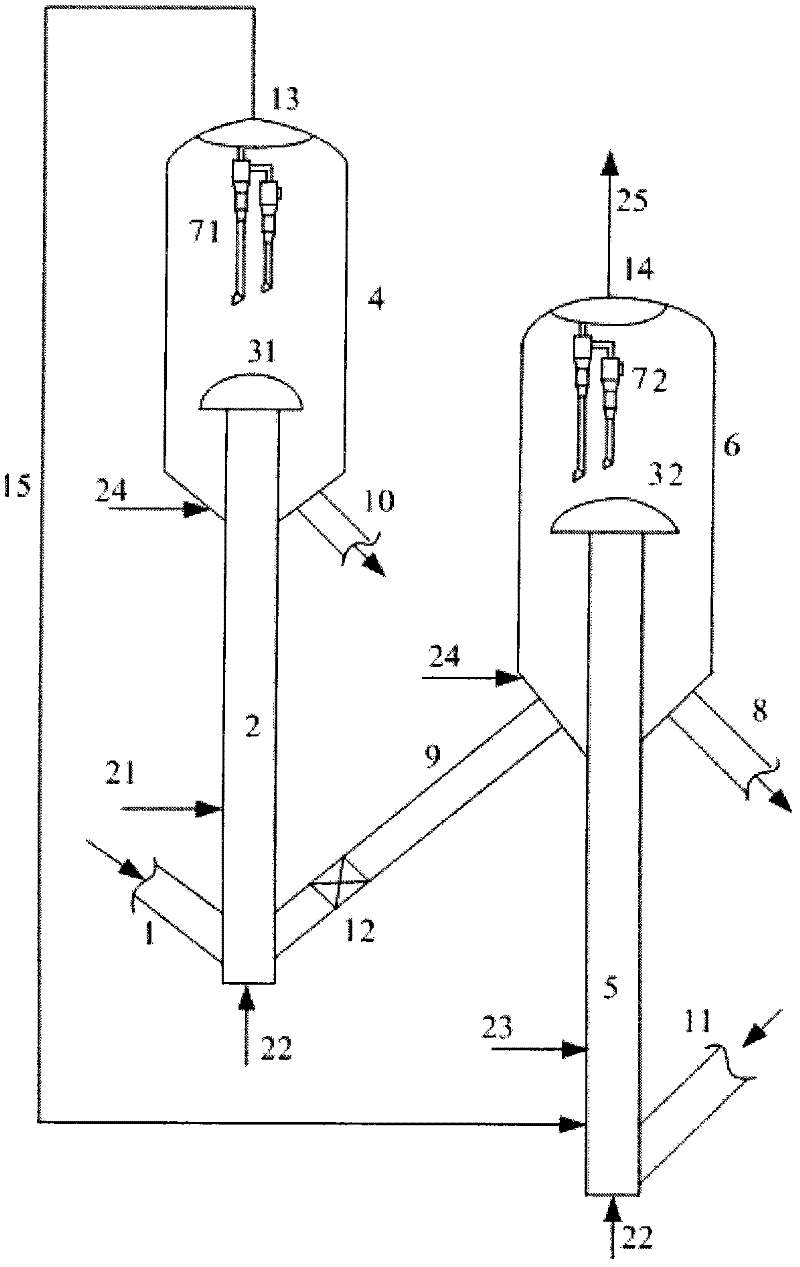
[0077] use figure 1 The hydrocarbon oil catalytic cracking equipment shown has a processing capacity of 2kg / h, the first reactor and the second reactor are both riser reactors, and the height ratio of the first reactor 2 and the second reactor 5 is 1:1.5 , the diameter ratio is 1:1. The stripping medium is steam at a temperature of 250°C. The catalysts used in the first reactor 2 and the second reactor 5 are MLC-500 balancer. This embodiment is for the purpose of producing more light oil (gasoline+diesel oil), the temperature of the second reactor 5 is lower than the temperature of the first reactor 2, and the oil agent contact time of the second reactor 5 is higher than that of the first reactor 2 Oil contact time, reaction conditions and results are shown in Table 3.

Embodiment 4-6

[0083] This example is used to illustrate the hydrocarbon oil catalytic cracking equipment and hydrocarbon oil catalytic cracking method provided by the present invention.

[0084] The catalytic cracking of hydrocarbon oil was carried out according to the method of Example 1, the difference was that the feed oil was feed oil B, and the catalysts in the first reactor and the second reactor were both MMC-2 catalysts. This embodiment aims at producing more light olefins, the temperature of the second reactor 5 is higher than the temperature of the first reactor 2, and the reaction conditions of the second reactor 5 are more severe than the first reactor 2, reaction conditions and results See Table 4.


PUM


Abstract

The invention discloses a catalytic cracking method for hydrocarbon oil. The method is characterized by comprising the following steps of: (1) undergoing a first contact reaction on a hydrocarbon oil raw material and a first cracking catalyst in a first reactor, and performing first oil-agent separation on a mixture of oil gas and the catalyst after the first contact reaction; (2) undergoing a second contact reaction on oil gas obtained after first oil-agent separation and a second newly-added cracking catalyst in a second reactor, and performing second oil-agent separation; and (3) feeding a part of or all of a spent catalyst obtained in the step (2) into the first reactor. The invention further provides catalytic cracking equipment for hydrocarbon oil. Due to the adoption of the method and the equipment, the problem of poor activity in the second reactor caused by great reduction in the activity of the catalyst discharged from the first reactor is solved, and the yields of dry gas and coke can be lowered greatly.

Description

technical field [0001] The invention relates to a hydrocarbon oil catalytic cracking method and hydrocarbon oil catalytic cracking equipment. Background technique [0002] Catalytic cracking is one of the most important secondary processing methods in the field of petroleum refining. [0003] Judging from the development in recent years, catalytic cracking technology will continue to develop around the following main aspects: [0004] Process heavy raw materials. Due to the growing demand for light oil and the increase in crude oil prices, the use of catalytic cracking technology to process heavy and low-quality feedstock oils such as atmospheric residues, vacuum residues, coker wax oils and deasphalted oils can yield greater economic benefits. How to solve the problems of serious heavy metal contamination of the catalyst and high coke yield when processing heavy raw materials is an important direction in the development of catalytic cracking technology. [0005] A new p...

Claims


Application Information

Patent Timeline
Patent Type & Authority Applications(China)
IPC IPC(8): C10G51/02
Inventor 李强常学良鲁维民杨克勇
Owner CHINA PETROLEUM & CHEM CORP
Why Eureka
Try Eureka