Hydrocarbon oil catalytic cracking method and equipment

A technology for catalytic cracking and hydrocarbon oil, applied in the field of hydrocarbon oil catalytic cracking and hydrocarbon oil catalytic cracking equipment, can solve the problems of weakened catalytic effect, large gas-solid back mixing, and decreased catalyst activity.

Active Publication Date: 2012-05-09
CHINA PETROLEUM & CHEM CORP +1
View PDF9 Cites 5 Cited by
  • Summary
  • Abstract
  • Description
  • Claims
  • Application Information

AI Technical Summary

Problems solved by technology

However, due to the gas-solid co-current flowing against the gravity field, there is a large axial and radial flow inhomogeneity in the riser, large gas-solid backmixing, uneven residence time distribution, etc., and the coke generated during the reaction is deposited on the catalyst. On the surface and active center, the activity of the catalyst drops sharply
Studies have shown that the current catalyst activity at the outlet of the riser is only about 1 / 3 of the initial activity, and the reaction takes about 1 second, and the catalyst activity drops by about 50%.
In this way, in the second half of the riser reactor, the activity of the catalyst drops sharply, the catalytic effect is greatly weakened, the thermal cracking reaction increases, more dry gas is produced and the olefin content of gasoline is increased.

Method used


Image

  • Hydrocarbon oil catalytic cracking method and equipment
  • Hydrocarbon oil catalytic cracking method and equipment
  • Hydrocarbon oil catalytic cracking method and equipment

Examples


Embodiment approach

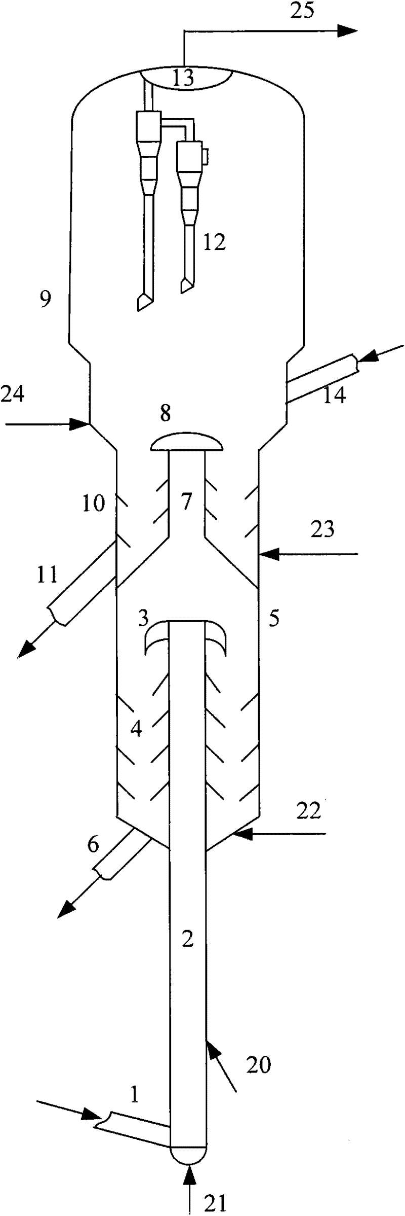
[0048] According to one embodiment of the present invention, preferably, as figure 1 As shown, the hydrocarbon oil catalytic cracking equipment provided by the present invention also includes the second stripping section 10 positioned at the lower part of the fluidized bed reactor 9, used for stripping the reacted catalyst in the fluidized bed reactor 9, the second stripping section 10 The lower part of the section 10 is also communicated with a second spent agent output pipe 11 and a second stripping medium input pipe 23 . The second spent agent output pipe 11 may communicate with the first stripping section 4, or directly communicate with the catalyst regenerator.

[0049] According to the present invention, each of the first stripping section 4 and the second stripping section 10 is preferably provided with a stripping baffle. The arrangement of the stripping baffle is well known to those skilled in the art, and will not be repeated here.

[0050] Further preferably, a ga...

Embodiment 1-3

[0064] This example is used to illustrate the hydrocarbon oil catalytic cracking equipment and hydrocarbon oil catalytic cracking method provided by the present invention.

[0065] use figure 1 The hydrocarbon oil catalytic cracking equipment shown has a processing capacity of 2 kg / h, the height ratio of the riser reactor 2 and the fluidized bed reactor 9 is 2:1, and the diameter ratio is 1:5. The raw material oil is first reacted in the riser reactor 2, and then the oil gas after the deactivated catalyst is separated by the inertial separator 3 is introduced into the fluidized bed reactor 9 to continue the reaction, and the oil gas and catalyst mixture after the reaction are subjected to oil separation , the catalyst after the oil agent separation and the inertial separator 3 separate the deactivated catalyst to obtain the raw catalyst after stripping, and the stripping medium is water vapor at a temperature of 250°C. The catalyst used in riser reactor 2 and fluidized bed re...

Embodiment 4-6

[0071] This example is used to illustrate the hydrocarbon oil catalytic cracking equipment and hydrocarbon oil catalytic cracking method provided by the present invention.

[0072] Carry out the catalytic cracking of hydrocarbon oil according to the method for embodiment 1, difference is that feedstock oil is feedstock B, the catalyst that riser reactor 2 adopts is MLC-500 balance agent, the catalyst that fluidized bed reactor 9 adopts is MMC -2 Catalyst. This embodiment is for the purpose of producing more low-carbon olefins (gasoline+diesel oil), the temperature of the fluidized bed reactor 9 is higher than the temperature of the riser reactor 2, and the reaction conditions of the fluidized bed reactor 9 are higher than that of the riser reactor 2. More severe, reaction conditions and results are shown in Table 4.


PUM


Abstract

The invention relates to a hydrocarbon oil catalytic cracking method which is characterized by comprising the following steps of: (1) carrying out first contact reaction on a hydrocarbon oil raw material and a first cracking catalyst in a lifting pipe reactor and carrying out first oil separation on a mixture of oil gas and a catalyst obtained after the first contact reaction; (2) carrying out a second contact reaction on the oil gas obtained after the first oil separation and a newly added second cracking catalyst in a fluidized bed reactor and carrying out second oil separation. The invention also provides hydrocarbon oil catalytic cracking equipment. On one hand, the problem of inadequate activity in the fluidized bed reactor, caused by the great reduction of the activity of the catalyst discharged out of the lifting pipe reactor, can be avoided, on the other hand, because the product obtained after reaction in the lifting pipe reactor is directly conveyed into the fluidized bed reactor without separation, the defect of increase of energy consumption, caused by repeated cooling and gasifying of feed materials can be avoided.

Description

technical field [0001] The invention relates to a hydrocarbon oil catalytic cracking method and hydrocarbon oil catalytic cracking equipment. Background technique [0002] Catalytic cracking is one of the most important secondary processing methods in the field of petroleum refining. [0003] Judging from the development in recent years, catalytic cracking technology will continue to develop around the following main aspects: [0004] Process heavy raw materials. Due to the growing demand for light oil and the increase in crude oil prices, the use of catalytic cracking technology to process heavy and low-quality feedstock oils such as atmospheric residues, vacuum residues, coker wax oils and deasphalted oils can yield greater economic benefits. How to solve the problems of serious heavy metal contamination of the catalyst and high coke yield when processing heavy raw materials is an important direction in the development of catalytic cracking technology. [0005] A new p...

Claims


Application Information

Patent Timeline
Patent Type & Authority Applications(China)
IPC IPC(8): C10G51/02
Inventor 杨克勇李强常学良鲁维民
Owner CHINA PETROLEUM & CHEM CORP
Why Eureka
Try Eureka