Cable railway system

A technology for cableways and cable cars, applied in the field of cableway systems, can solve problems such as increased wear of support rollers

Active Publication Date: 2012-05-16
INNOVA PATENT GMBH
View PDF4 Cites 7 Cited by
  • Summary
  • Abstract
  • Description
  • Claims
  • Application Information

AI Technical Summary

Problems solved by technology

However, due to the vertical movement of the transmission cable, different loads occur on the at least one supporting roller, the loading of the supporting rollers causing increased wear on the at least one supporting roller

Method used


Image

  • Cable railway system
  • Cable railway system
  • Cable railway system

Examples


Embodiment Construction

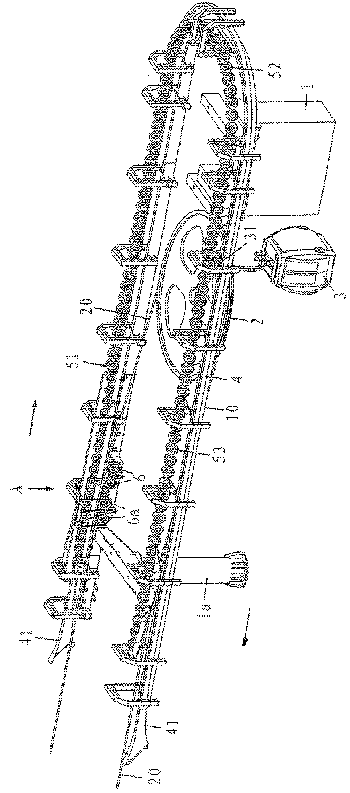
[0022] Reference is now made to the figure numbers of the accompanying drawings in detail and first in particular to figure 1 , which shows a terminal station with a load supporting structure 10 supported by columns 1 and 1a and on which a deflection pulley 2, also called a head wheel, is mounted on an approximately vertical axle , is guided via the pulley transmission cable 20 . During operation of the funicular cableway system, the transmission cable 20 is run at a speed of eg 6 m / s by means of a drive motor located preferably at the top station. The transport vehicle 3 , in the present case the gondola, can be connected to the transmission cable 20 . On the road, the motor vehicle 3 is connected to the transmission cable 20 . At the entrance to the station, the motor vehicle 3 is detached from the transmission cable 20 and moved through the station along the guide rail 4 by means of a running transmission 31 . At the exit of the station, the vehicle 3 is reconnected to t...


PUM


Abstract

A cable railway system has a conveying cable, which in the two end stations of the system is guided over a respective deflection pulley. Transport vehicles, which can be coupled to the conveying cable and are configured with a clamping device and with a running gear. The vehicles are coupled to the conveying cable along the route and are guided in the stations by way of the running gear along guide rails. There, the passengers disembark and board. The movement of the vehicles in the stations is governed by control tires, which are drivingly coupled to one another by gear mechanisms. The drive power of the control tires is taken from at least one support roller for the conveying cable, which support roller is located in the station. The support roller for the conveying cable via which the drive of the control tires is derived from the conveying cable by way of at least one drive belt is elastically mounted on a rigidly fastened axle.

Description

[0001] Cross References to Related Applications [0002] This application claims priority under 35 U.S.C 119 to Austrian Patent Application A1729 / 2010 with a filing date of October 18, 2010; the earlier application is hereby incorporated by reference in its entirety. technical field [0003] The invention relates to a funicular cableway system having a transmission cable which is guided between two terminal stations of the system by respective deflection pulleys or head wheels. The system includes motor vehicles, such as gondolas, cars or chairlifts, which are connectable to the transmission cables and are equipped with clamping devices and transmission mechanisms. Motor vehicles are connected to the transmission cable along the route and are separated from the transmission cable at the entrance into the station, they are guided by the transmission mechanism along the guide rail through the station, so passengers board and disembark and reconnect to the transmission at the exi...

Claims


Application Information

Patent Timeline
Patent Type & Authority Applications(China)
IPC IPC(8): B61B7/04B61B12/02
CPCB61B12/04B61B12/105B61B12/022
Inventor M.贝克
Owner INNOVA PATENT GMBH
Why Eureka
Try Eureka