Rotor with integral tension torque transfer element and method of production thereof

A torque transmission and rotor technology, applied in the rotor field, can solve problems such as short service life, unobvious sudden failure, lack of wear resistance of connecting bundles, etc., and achieve the effect of simplified production

Active Publication Date: 2015-08-19
AIRBUS HELICOPTERS DEUT GMBH
View PDF9 Cites 0 Cited by
  • Summary
  • Abstract
  • Description
  • Claims
  • Application Information

AI Technical Summary

Problems solved by technology

Although the production of the rotor blades, especially the connecting bundles in the end region, appears to be simple, the rotor blades, especially the connecting bundles, produced in this way lack wear resistance and have an extremely short service life
Their sudden failures are not obvious and even difficult to detect during inspection
Therefore, this rotor blade does not provide a viable solution

Method used


Image

  • Rotor with integral tension torque transfer element and method of production thereof
  • Rotor with integral tension torque transfer element and method of production thereof
  • Rotor with integral tension torque transfer element and method of production thereof

Examples


Embodiment Construction

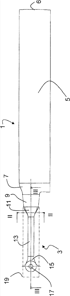
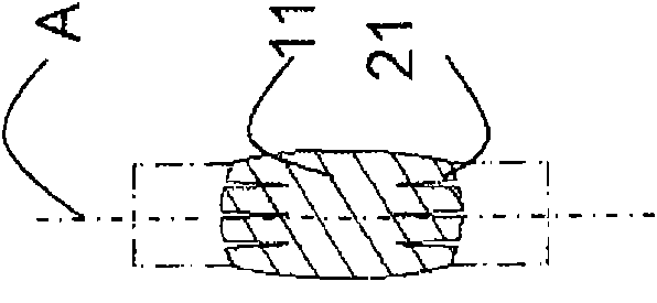
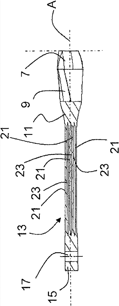
[0060] according to figure 1 The rotor basically consists of rotor blades 1 and tension torque transfer elements 3 . A tension torque transmission element 3 connects the rotor blade 1 to the hub of a drive device (not shown). The rotor blade 1 and the tensioning torque transmission element 3 are designed in one piece, with a blade transition section 7 following the blade section 5 of the rotor blade 1 on the hub side and a torque transmission section 9 on the hub side. Starting from the torque transmission section 9 , the tension torque transmission element 3 adjoins the blade-side connection section 11 , which, in particular, exhibits a largely conical transition in plan view to a considerably thinner rectangular torque transmission Element 13. The torque transmission element 13 is enlarged on the hub side to form a rod-shaped connecting section 15 which accommodates a circular connecting eye 17 extending vertically through said connecting section 15 . The dashed line show...


PUM


Abstract

The invention discloses a rotor wing with a fiber-reinforced composite design. The rotor wing comprises fiber layers, in particular fiber layers for a tail rotor wing of a rotorcraft. The rotor wing is provided with a rotor wing blade (1), a tension-torque-transmission element (3) and fiber layers (42-47), wherein the rotor wing blade (1) comprises blade surface layers (40, 50) and blade bodies (41-57); the blade bodies comprise effective aerodynamic molding surfaces; the tension-torque-transmission element (3) is connected to the rotor wing, and is designed together with the rotor wing blade (1) into a piece; and these fiber layers extend through the tension-torque-transmission element (3), and are embedded into the rotor wing blade (1). An improvement on the rotor wing is that: these fiber layers (42-47) directly extend from the tension-torque-transmission element (3) to the blade bodies (41-57). Moreover, the invention describes a method for producing the rotor wing.

Description

technical field [0001] The invention relates to a rotor of fibre-reinforced composite design comprising fiber layers, in particular for the tail rotor of a rotorcraft or a helicopter. The rotor comprises a rotor blade and a tension torque transfer element, the rotor blade has a blade surface and a blade body, the blade body comprises an aerodynamically effective profile, the tension torque transfer element is connected to the rotor blade and is designed in one piece with the rotor blade . A fiber layer extends through the tension torque transfer element and is contained within the rotor blade. The invention also relates to a method of producing the rotor. Background technique [0002] For weight- and cost-related reasons, particularly in aircraft construction, there is an increasing attempt to replace elements made of metal with components produced in fiber-reinforced composite designs. Due to their geometry, these components need to be adapted to the design. The parts a...

Claims


Application Information

Patent Timeline
Patent Type & Authority Patents(China)
IPC IPC(8): B64C27/467
Inventor G·昆特茨-费切纳
Owner AIRBUS HELICOPTERS DEUT GMBH
Why Eureka
Try Eureka