Remote-control-based light-emitting diode (LED) display screen

A technology of LED display and remote control, applied in signal transmission systems, instruments, identification devices, etc., can solve the problem that LED luminous characters do not have a three-dimensional sense.

Inactive Publication Date: 2012-05-16
HEBEI UNIVERSITY OF SCIENCE AND TECHNOLOGY
View PDF4 Cites 3 Cited by
  • Summary
  • Abstract
  • Description
  • Claims
  • Application Information

AI Technical Summary

Problems solved by technology

[0003] The purpose of this invention is to solve the problem that the LED luminous characters do not have a three-dimensional effect in the prior art, and design a LED display screen based on remote control. By building a model, motors and rigid LED lights are set on each side of the model The signal lines of the LED lights on the rigid LED light bar are connected in parallel to the control unit. When all the motors are rotating, the four sides will display images.

Method used


Image

  • Remote-control-based light-emitting diode (LED) display screen
  • Remote-control-based light-emitting diode (LED) display screen
  • Remote-control-based light-emitting diode (LED) display screen

Examples


Embodiment Construction

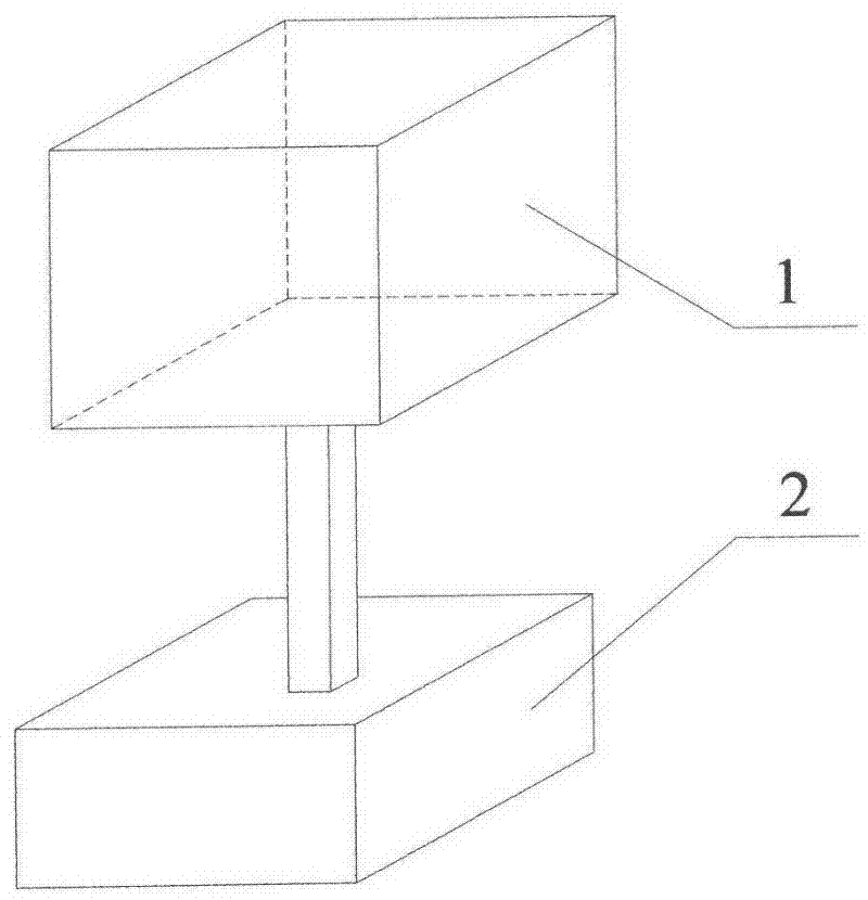
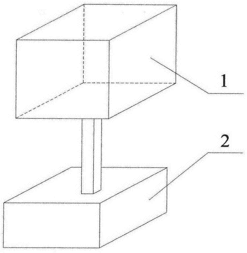
[0010] An LED display screen based on remote control, the structure includes a columnar display screen surrounded by upper and lower end faces and at least three transparent sides 1, and the columnar display screen is positioned on a base 2 equipped with a wireless transceiver module, The key is: a motor is positioned on each transparent side 1 in the columnar display, a rigid LED light bar is installed on the motor shaft, the input end of the motor is connected to the drive circuit, and the signal of the LED sequence on the rigid LED light bar is controlled The terminal is connected to the remote control unit by means of a wireless transceiver module.

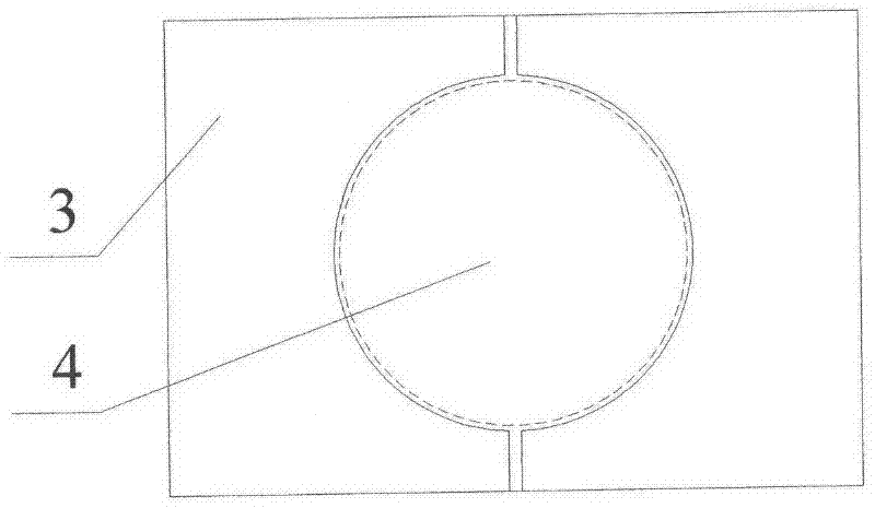
[0011] The LED sequences on all the rigid LED light strips are numbered in sequence, and the signal controlled ends of the LED lights with the same number are connected in parallel to the remote control unit. The LED light-emitting surface of the above-mentioned rigid LED light bar is a curved surface. The above-mentioned cur...


PUM


Abstract

The invention discloses a remote-control-based light-emitting diode (LED) display screen, which solves the problem that an LED channel letter in the prior art is lack of stereoscopic sensation. One-surface imaging in the prior art is changed into multi-surface simultaneous imaging, a plurality of surfaces are connected end to end to form an enclosed display screen space at the same time, a rigid LED light bar is driven by the rotation of all side motors to rotate, lights on the rigid LED light bar are turned on and off to form a certain circular pattern due to a visual persistence effect when the rotating speed of each motor reaches a certain degree, and LED light beads on the rigid LED light bar are controlled to be turned on and off to form a designed pattern when the rotating speed of each motor is relatively higher.

Description

technical field [0001] The invention relates to an LED luminous imaging technology, which utilizes the persistence of vision effect to rotate and form images, and can be applied to advertising, lighting and decoration, in particular to a display method and an LED display that can improve the stereoscopic effect of LED luminous images. Background technique [0002] LED luminous character technology has been applied to all aspects of advertising life, and has played an irreplaceable role in advertising. The traditional technology adopts array method and program control technology to form LED luminous characters, which has high cost, complicated control, and inconvenient maintenance. Moreover, once some LED units in the array fail, the overall effect of LED luminous characters will be affected. Therefore, the LED lighting technology that relies on motor rotation has gradually entered people's field of vision. The imaging principle of the LED luminous characters that rely on mo...

Claims


Application Information

Patent Timeline
Patent Type & Authority Applications(China)
IPC IPC(8): G09F9/33G08C17/02
Inventor 霍彦明李争郑毅琳董若凡梁国壮
Owner HEBEI UNIVERSITY OF SCIENCE AND TECHNOLOGY
Why Eureka
Try Eureka