
Drill bit

A drill bit and sub-face technology, applied in twist drills, drill accessories, drilling/drilling equipment, etc., can solve problems such as drill bit breakage, and achieve the effect of large cutting angles

Inactive Publication Date: 2014-04-16
MAPAL FABRIK FUER PRAEZISIONSWERKZEUGE (DE)
View PDF7 Cites 0 Cited by
  • Summary
  • Abstract
  • Description
  • Claims
  • Application Information

AI Technical Summary

Problems solved by technology

The result of insufficient coordination between edge stability and chip flute size is the risk of drill breakage in the area of ​​the center edge

Method used


Image

  • Drill bit
  • Drill bit
  • Drill bit

Examples


Embodiment Construction

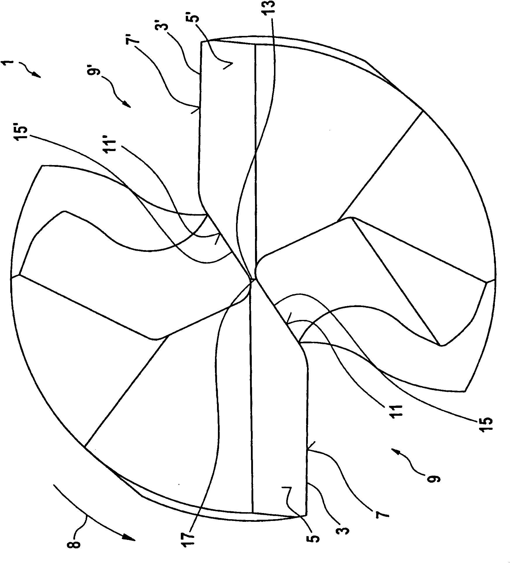
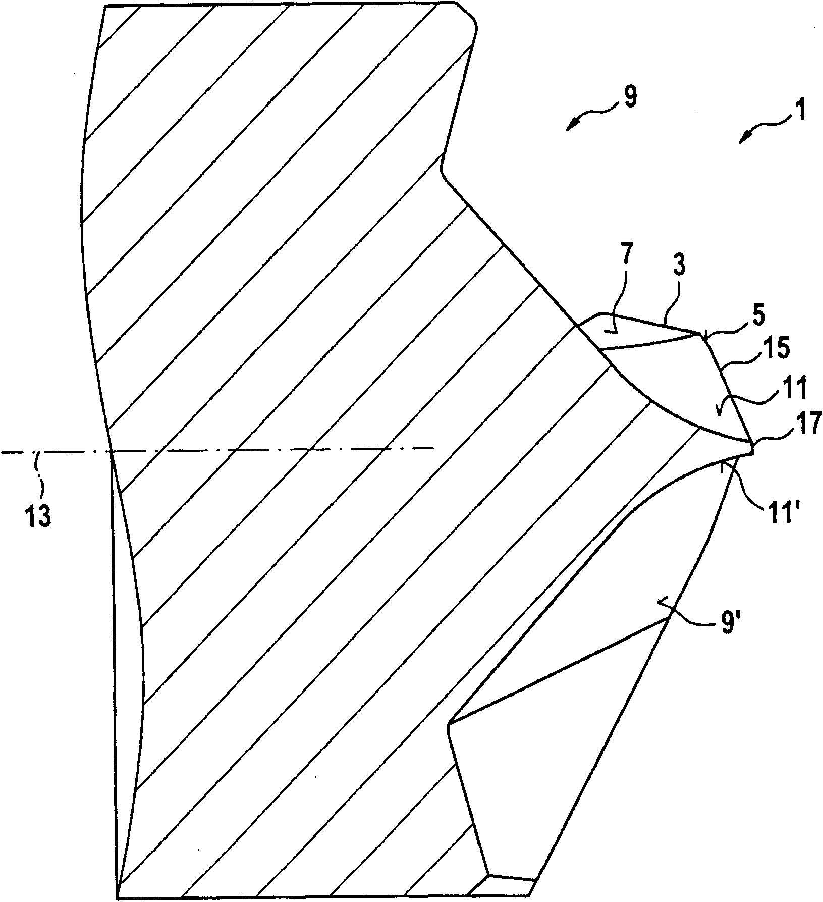
[0023] figure 1 A front view of a known drill bit 1 is shown, which has a conventional geometry with sharpening. The drill comprises at least one main cutting edge, to be precise here two main cutting edges 3 and 3'. The main cutting edges 3 and 3' are each formed by the intersection of the free surface 5, 5' and the cutting surface 7, 7'. The free faces 5 , 5 ′ follow the main cutting edges 3 and 3 ′ in the cutting direction, which here means the direction of rotation of the drill when machining the workpiece. In this embodiment, this direction is opposite to the clockwise direction and is indicated by arrow 8 . The free surfaces 5 , 5 ′ fall opposite to the cutting direction so that they form an angle with a plane parallel to the machined surface of the workpiece, which is referred to as the free angle (Freiwinkel). The chips removed from the workpiece by the main cutting edges 3 and 3' are discharged from the cutting faces 7, 7'. The cutting faces 7, 7' form an angle wi...


PUM


Abstract

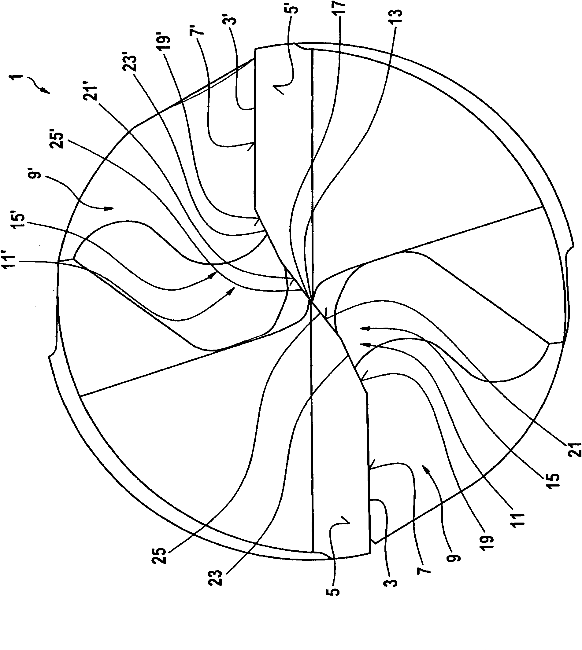
The invention proposes a drill bit (1) leaving at least one main cutting edge (3, 3′) and at least one center cutting edge (15, 15′), wherein the drill bit (1) comprises a longitudinal axis (13), and wherein the at least one main cutting edge (3, 3′) and the at least one center cutting edge (15, 15′) are each assigned a rake face (7, 7′, 11, 11′). The drill bit (1) is characterized in that the rake face (11, 11′) assigned to the at least one center cutting edge (15, 15′) has at least two part faces (19, 19′; 21, 21′) which—as seen as perpendicular to the longitudinal axis (13) of the drill bit (1)—form an obtuse angle with one another, so that the at least one center cutting edge (15, 15′) comprises at least two part cutting edges (23, 23′; 25, 25′).

Description

technical field [0001] The invention relates to a drill having at least one main cutting edge and at least one center edge, wherein the drill has a longitudinal axis and the at least one main cutting edge and the at least one center edge are each associated with a cutting face. Background technique [0002] Drills of the type described are known. The drill has at least one main cutting edge extending from the peripheral surface of the drill substantially towards the center of the drill. In the central region of the drill bit a cutting zone is formed which is more precisely scraping and pressing rather than cutting because the wedge angle (Keilwinkel) in this cutting zone is significantly greater than in the radially outer cutting zone cutting. If the drill comprises two main cutting edges which are preferably arranged point-symmetrically to one another (visible in a top view of the drill end side), a chisel edge is provided in the central region of the drill which connects...

Claims


Application Information

Patent Timeline
Patent Type & Authority Patents(China)
IPC IPC(8): B23B51/02
CPCB23B51/02B23B2251/04B23B2251/18B23B2251/70Y10T408/909Y10T408/9097
Inventor 乌尔里希·克莱泽尔彼得·马茨
Owner MAPAL FABRIK FUER PRAEZISIONSWERKZEUGE (DE)
Learn More