
Winding and method for producing a winding

A winding and carrier technology, applied in the field of winding manufacturing

Inactive Publication Date: 2012-05-16
SIEMENS AG
View PDF9 Cites 5 Cited by
  • Summary
  • Abstract
  • Description
  • Claims
  • Application Information

AI Technical Summary

Problems solved by technology

Coil windings, especially for low-voltage and high-voltage windings, can currently only be produced in multiple and expensive work steps

Method used


Image

  • Winding and method for producing a winding
  • Winding and method for producing a winding
  • Winding and method for producing a winding

Examples


Embodiment Construction

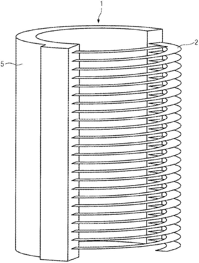
[0025] figure 1 A perspective view showing winding 1. exist figure 1 In the example shown, electrical conductors 3 a , 3 b , 3 c , 3 d (not shown) and at least partially electrically insulating layers 4 a , 4 b , 4 c are arranged on a carrier 2 . The carrier 2 has a curved shape which corresponds to the radius of the winding 1 . exist figure 1 In the example shown, the electrically insulating layers 4a, 4b, 4c are secured by a casing 5 of cast resin. This makes it possible to arrange the respective electrical conductors 3 a , 3 b , 3 c , 3 d on the carrier 2 and to have the respective potting resin jacket 5 completely surround the carrier 2 during subsequent processing. Based on the electrical insulation properties of the casting resin jacket 5, the casting resin jacket fulfills the function of the electrical insulating layers 4a, 4b, 4c.

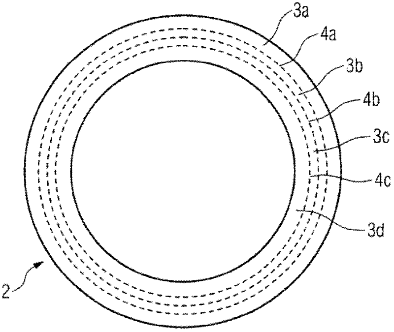
[0026] figure 2 A top view of a carrier 2 with four electrical conductors 3a, 3b, 3c, 3d is shown. Between the individual electric...


PUM


Abstract

The invention relates to a winding having a wound electrical conductor, wherein the electrical conductor comprises an electrical insulator. The invention further relates to a method for producing a winding. By using a carrier on which the electrical conductor can be arranged and is electrically insulated, the winding can be produced as a single piece. The carrier is particularly implemented in the form of a cylindrical spiral as a coil, and thereby allows practically unlimited single-piece production of the winding. The cross section and / or the width of the electrical conductor can simultaneously be varied by location on the carrier.

Description

technical field [0001] The invention relates to a winding comprising a wound electrical conductor, wherein the electrical conductor has an electrical insulation layer. Furthermore, the invention relates to a winding production method. Background technique [0002] Manufacture of power transformers as cast resin transformers or as distribution transformers for high-voltage power grids is a very labor-intensive and cost-intensive process. Coil windings, in particular for low-voltage and high-voltage windings, can currently only be produced using multiple and expensive work steps. For this purpose, the winding wire is wound into component windings on a winding machine to achieve the necessary winding diameter. The partial windings produced in this way are then connected to one another by means of corresponding connecting elements to form low-voltage or high-voltage windings, as described, for example, in DE 198 09 572 C2. [0003] DE2609548C2 also introduces a winding device...

Claims


Application Information

Patent Timeline
IPC IPC(8): H01F5/00
CPCH01F27/327H01F41/0608H01F27/2847H01F41/122H01F27/2804H01F27/323H01F41/063Y10T29/49071
Inventor R.哈诺夫
Owner SIEMENS AG
Learn More