Subglottic suctioning system

A suction system, glottis technology, applied in suction and irrigation systems, respirator, suction equipment, etc., can solve problems such as unsatisfactory

Active Publication Date: 2012-05-23
AVENT INC
View PDF12 Cites 4 Cited by
  • Summary
  • Abstract
  • Description
  • Claims
  • Application Information

AI Technical Summary

Problems solved by technology

Clearly, these solutions are unsatisfactory due to the

Method used


Image

  • Subglottic suctioning system
  • Subglottic suctioning system
  • Subglottic suctioning system

Examples


Embodiment Construction

[0032]Referring now to the drawings, in which the various parts herein will be numbered and the present disclosure will be described in detail to enable those skilled in the art to make and use the same. It should be understood that the following description is only illustrative of the principles of the invention and should not be taken as limiting the appended claims. Those skilled in the art will recognize that the various embodiments described in detail can be interchanged and modified without departing from the scope and spirit of the invention.

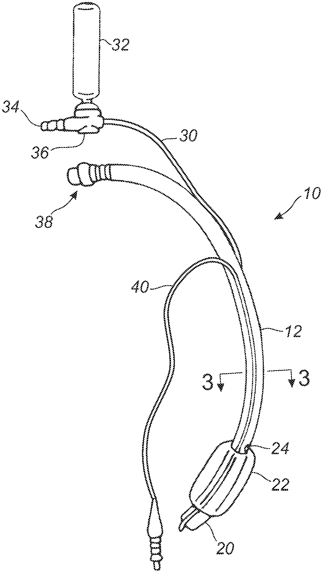
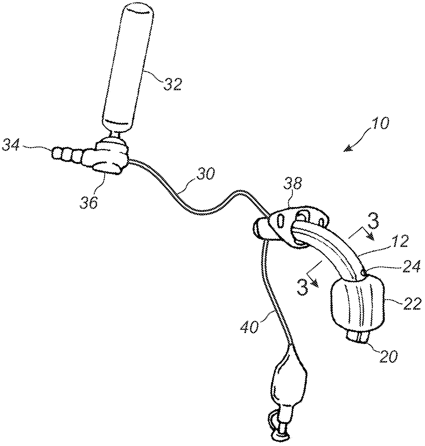
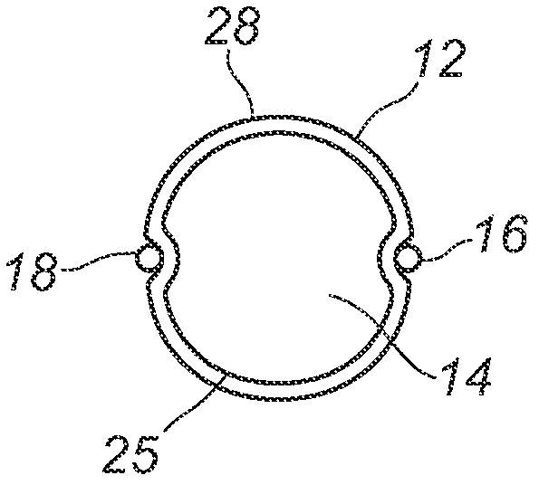
[0033] see figure 1 , figure 2 with image 3 , describing an endotracheal tube 10 according to two embodiments of the invention. figure 1 shows the endotracheal tube, figure 2 showing the tracheostomy tube, image 3 shown in figure 1 or figure 2 The cross-sectional view taken at 3-3 in .

[0034] The endotracheal tube 10 in the illustrated embodiment is a multi-lumen tube 12 having at least one breathing lumen 14 , at ...


PUM


Abstract

A subglottic suctioning system with a tracheal tube (10) having a ventilation lumen, a cuff inflation lumen (14), and a suction lumen (16) are disclosed which may help reduce the incidence of ventilator associated (or acquired) pneumonia. The suction lumen communicates with the space in the trachea above the cuff (22) where secretions accumulate. The suction lumen has a valve (36) on the proximal end for connection to a source of vacuum. The valve is adapted to interrupt the supply of vacuum to the suction lumen to allow for the introduction of a rinsing fluid in its place and to automatically re-establish the connection to the source of vacuum upon completion of rinsing. The rinsing fluid aids in maintaining an open suction lumen and may include medicaments and mucolytic agents to enhance or promote healing or to alter the properties of the mucus to make removal easier. The user may easily and repeatedly alternate suction and rinsing fluid through the suction lumen, i.e., the user may 'pulse' the line to loosen, break up and remove secretions and deposits that may partially or completely block or clog the suction lumen.

Description

Background technique [0001] Endotracheal intubation involves inserting a hollow tubular member called an endotracheal tube into the patient's windpipe. The catheter can be inserted through the mouth or less ideally through the nose or can be inserted through the neck through an incision in the front of the throat. If the tube is inserted through the mouth or nose, it is called an endotracheal tube, and if the tube is inserted through the front of the throat, it is called a tracheostomy tube or endotracheal tube. Both types of tubes are referred to herein as endotracheal tubes. The endotracheal tube enters the trachea and terminates at a location above the carina, anterior to a location between the second and fourth thoracic vertebrae. Gas can then be introduced through the central lumen of the endotracheal tube and into the patient's lungs. [0002] The fundamental purpose of endotracheal intubation is to mechanically ventilate the patient's lungs when the patient is unable...

Claims


Application Information

Patent Timeline
IPC IPC(8): A61M16/04A61M1/00
CPCA61M16/0463A61M1/0084A61M16/04A61M1/0064A61M2016/0479A61M16/0465A61M2016/0486A61M16/0434A61M1/0062A61M16/0479A61M16/0486A61M16/0443A61M1/774A61M1/85A61M1/772A61M16/201A61M16/208
Inventor B·J·奎瓦斯J·A·凯萨S·M·特谢拉M·斯莱瓦A·A·赫尔希S·A·巴拉蒂安
Owner AVENT INC
Why Eureka
Try Eureka