Device for supplying inhalation gas to and removing exhalation gas from a patient

a technology for inhalation gas and patient, which is applied in the field of inhalation gas supply devices for inhalation gas supply and exhalation gas removal of patients, which can solve the problems of patient suffering significant stress, discomfort, and a sense of suffocation, and the ability of the tracheal tube used today to remove the secretion,

Inactive Publication Date: 2003-10-21
ALORO MEDICAL
View PDF49 Cites 61 Cited by
  • Summary
  • Abstract
  • Description
  • Claims
  • Application Information

AI Technical Summary

Problems solved by technology

In addition, the tracheal tubes, which are used today, do not have a satisfactory capability of removing the secretion since the same quantity of gas is transported successively in both directions through the channel of the tracheal tube.

Method used


Image

  • Device for supplying inhalation gas to and removing exhalation gas from a patient
  • Device for supplying inhalation gas to and removing exhalation gas from a patient
  • Device for supplying inhalation gas to and removing exhalation gas from a patient

Examples


Embodiment Construction

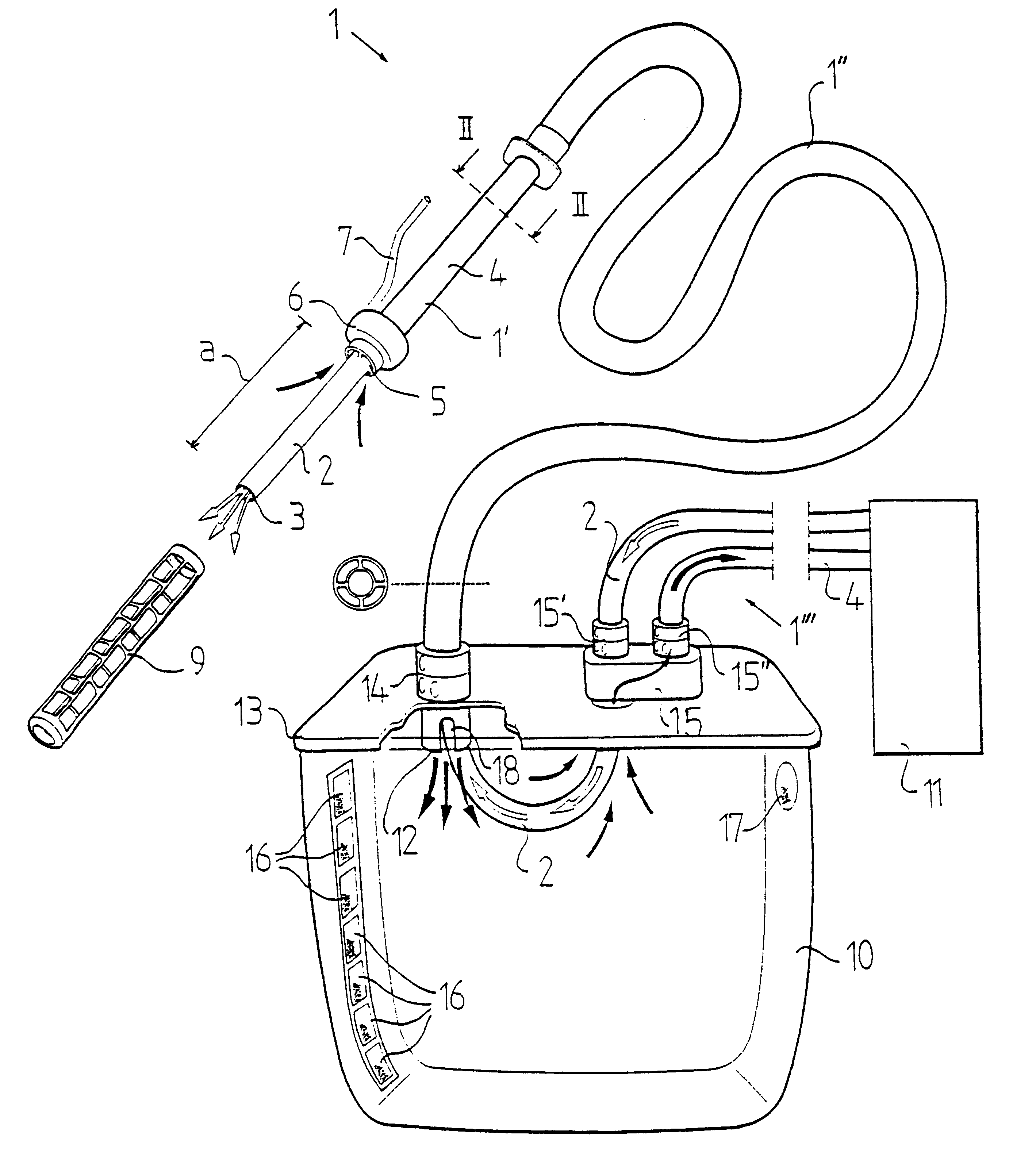
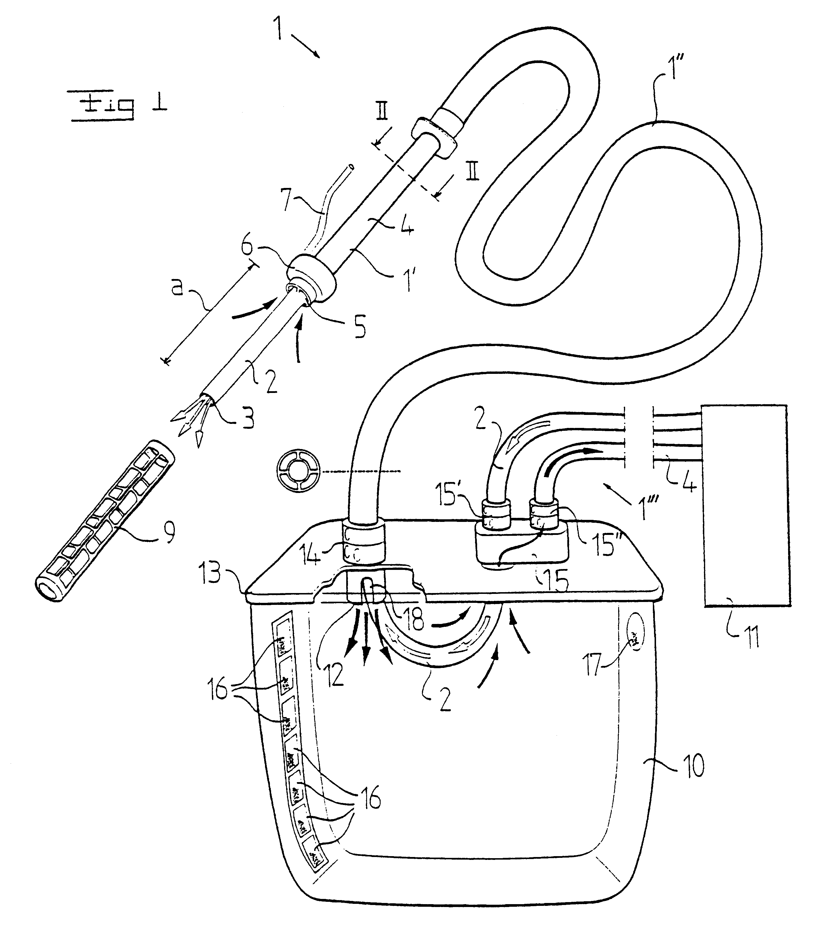
FIG. 1 discloses a device for the supply of inhalation gas to and the removal of exhalation gas from a patient. The device includes a pipe member 1 which is intended to be introduced into the trachea of a patient. The pipe member 1 includes a forward portion 1', which forms a so called endotracheal tube and which is intended to be located in the trachea and the throat of the patient, and a rearward portion 1", which may be connected to the forward portion 1' via a connecting member or be manufactured in one piece together with the forward portion 1'. In the embodiment disclosed, the rearward portion 1" is manufactured in a more flexible material than the forward portion 1'.

The pipe member 1 includes a first pipe conduit 2, which forms a first channel and is intended to transport said inhalation gas to the patient and which has a distal outlet opening 3 for the inhalation gas. Furthermore, the pipe member 1 includes a second pipe conduit 4, which forms a second channel and is arrange...


PUM


Abstract

An integrated tracheal tube/suction ventilation and co-committal secretion removal device having first and second coaxially arranged conduits where the first interior conduit forms a lumen to deliver gas, and a circumferentially arranged second conduit lumen is structurally adapted to serve as an integral suction lumen for removal of both expiratory gases and secretions. The distal end outlets of both lumens terminate between the device's fixing member and its distal end. The two lumen outlets are arranged such that relative to each other and the device the first interior pipe conduit forming lumen's outlet is located at the distal end and the second pipe conduit lumen's outlet is located at or near the distal side of the fixing member. This selection of relative positioning facilitates optimal deliver of breathing gas to a user in conjunction with removal of expiratory gases and secretions. The device is sized for location of the fixing member to its distal end from a patient's carina to a patient's larynx.

Description

THE BACKGROUND OF THE INVENTION AND PRIOR ARTThe present invention refers to a device for supplying inhalation gas to and removing exhalation gas from a patient, including a pipe member, suited to be introduced into the trachea of a patient and comprising a first pipe conduit, which is intended for said inhalation gas and has a distal outlet opening arranged to be positioned at the dividing region of the main bronchi of the patient during use of the device.The introduction of such devices for the supply of inhalation gas and the removal of exhalation gas, so called intubation, is made as a matter of routine in medical treatment of patients which need external breath support from a respirator. The device includes normally a plastic pipe, a so called endotracheal tube, which via the throat is guided down into the trachea to a position at the dividing region of the main bronchi. The endotracheal tube is fixed in the trachea by means of a fixing member which is provided slightly above t...

Claims


Application Information

Patent Timeline
IPC IPC(8): A61M16/04A61M1/00A61B17/00A61L2/16A61M16/00A61M16/08A61M25/00A61M25/10
CPCA61M1/0001A61M1/0096A61M16/042A61M16/0463A61M16/0434A61M2205/3382A61M1/882A61M1/60
Inventor FLODIN, BJORN
Owner ALORO MEDICAL
Why Eureka
Try Eureka