
Low-insertion-force connector

A low insertion force, connector technology, applied in the direction of connection, connecting device parts, coupling device, etc., can solve the problem of connector fitting and detachment, reduce rotation operation gap, promote gap saving, and promote compactness Effect

Active Publication Date: 2014-12-24
YAZAKI CORP
View PDF7 Cites 0 Cited by
  • Summary
  • Abstract
  • Description
  • Claims
  • Application Information

AI Technical Summary

Problems solved by technology

[0011] However, in the conventional low-insertion force connector described above, when the connector is mated and disengaged, a work space for the rotation lever 72 and the handle is required, and a work space for assembling the handle to the cam bolt is required. In the narrow space of automobiles such as hybrid vehicles, it is difficult to smoothly fit and disengage the connector
In addition, when performing vehicle maintenance, etc., when the motor and converter of equipment such as a hybrid vehicle are disconnected through a connector, it is necessary to install a safety circuit to avoid danger such as electric shock to the operator. However, in this error-free and space-saving intermittent operation of the safety circuit is necessary

Method used


Image

  • Low-insertion-force connector
  • Low-insertion-force connector
  • Low-insertion-force connector

Examples


Embodiment Construction

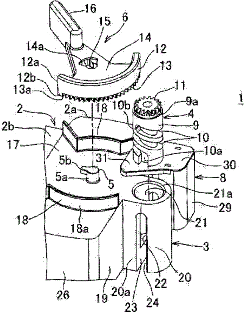
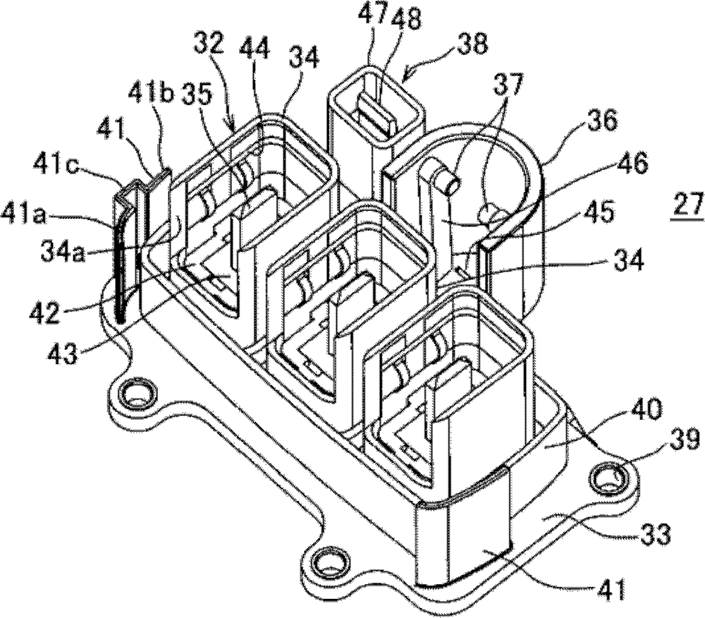
[0044] Figure 1 ~ Figure 2 It is a figure which shows the 1st Embodiment of the low insertion force connector concerning this invention. figure 1 Indicates the connector (female connector) that accommodates the female terminal, figure 2 It shows the other connector (male connector) that accommodates the male terminal, and two connectors constitute a low insertion force connector.

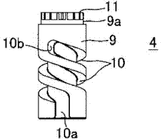
[0045] Such as figure 1 As shown, one connector 1 includes a connector housing 2 made of insulating resin and an L-shaped female terminal with a wire (not shown) housed in the connector housing 2 and is mounted on the connector housing 2. The cylindrical gear member 4 made of synthetic resin in the substantially cylindrical receiving portion 3, the drive rod 6 made of synthetic resin that is rotatably engaged with the shaft portion 5 of the connector housing 2 and meshes with the gear member 4, With the rail part 7 ( Figure 4 ) A safety circuit unit 8 that is slidably engaged and can be slidably mo...


PUM


Abstract

For connection and disconnection of both connectors with ease and assurance in a narrow work space and connection, and for disconnection of a safety circuit unit without mistakes and in a saved-space, a low-insertion-force connector assembly 53 is provided with one connector receiving the one terminal and other connector 27 receiving a mating terminal, wherein the one connector includes a driving lever 6 having a rotative circular-arc-shaped gear part 13, and, pivotally supported along a wall part 17 of the one connector, a gear wheel part 11 engaged with the gear part, and a gear member 4 having a spiral groove engaged with a driven projection 37 of the other connector, wherein the safety circuit unit 8 is slidably disposed in the one connector, a small connector 38 for connection is disposed in the other connector, thereby the driving lever 6, at a provisional position, prevents the safety circuit unit from rotating in a connecting direction of the safety circuit unit, and, at a connecting position, allows the safety circuit unit to move and is blocked to rotate by a flange 31.

Description

Technical field [0001] The present invention relates to a low insertion force connector that is used to rotate a drive rod to disengage male and female connectors and prevent sparks during disengagement. Background technique [0002] Figure 15 This is a diagram showing one aspect of a conventional low insertion force connector (see Patent Document 1). [0003] The low insertion force connector 71 is for electrically connecting the motor and the converter of, for example, a hybrid vehicle. By turning the lever 72 in the direction of the arrow, the counterpart connector (not shown) is pulled closer to make it Fitting parts. [0004] The lever 72 is rotatably engaged with the shaft portion on the side of the connector housing 73. The lever 72 is provided with a cam groove 74 for slidingly engaging the driven protrusion (not shown) of the counterpart connector. The rod 72 in the erected state is rotated to the rear as shown by the arrow, and the counterpart connector is pulled in and f...

Claims


Application Information

Patent Timeline
Patent Type & Authority Patents(China)
IPC IPC(8): H01R13/629H01R13/66
CPCH01R13/62944Y10S439/9242H01R13/665H01R13/7038
Inventor 冈本健一石川步矢込佐知子
Owner YAZAKI CORP
Learn More