
Power transmission line steel tube tower and construction method thereof

A technology for transmission lines and steel pipe towers, which is applied to the spatial arrangement/configuration of towers and cables, building types, etc., can solve problems such as the impact of reliability data, and achieve reduction of construction personnel and labor, short external power outages, and input lines. The effect of less hardware material

Inactive Publication Date: 2012-05-30
江苏省电力公司吴江市供电公司 +3
View PDF5 Cites 4 Cited by
  • Summary
  • Abstract
  • Description
  • Claims
  • Application Information

AI Technical Summary

Problems solved by technology

[0010] Under the premise that a crane can be used to erect steel pipe towers, such power outage construction generally takes about 8 hours. In the current environment where reliability requirements for power transmission and transformation are increasing, it will have a great impact on reliability data

Method used


Image

  • Power transmission line steel tube tower and construction method thereof
  • Power transmission line steel tube tower and construction method thereof

Examples


Embodiment Construction

[0025] The technical implementation process of the present invention will be further described below in conjunction with the accompanying drawings and embodiments.

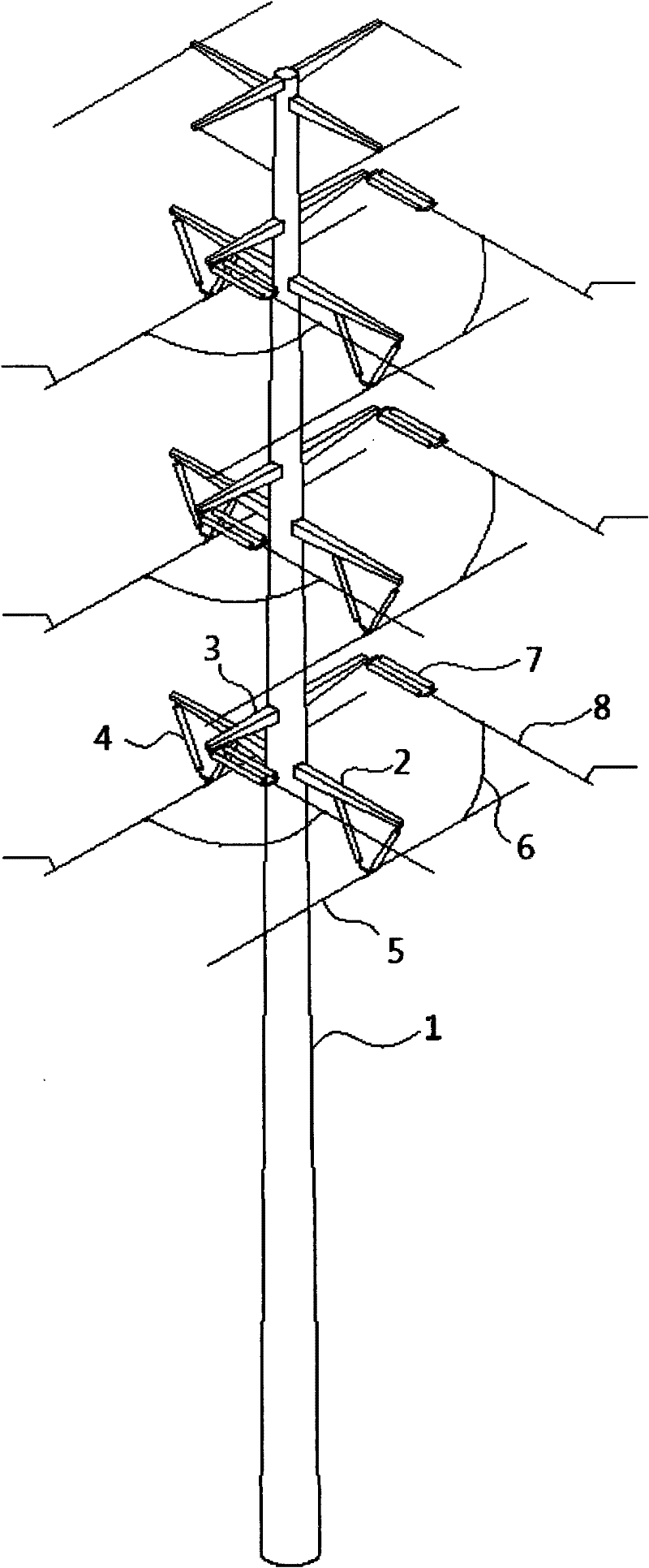
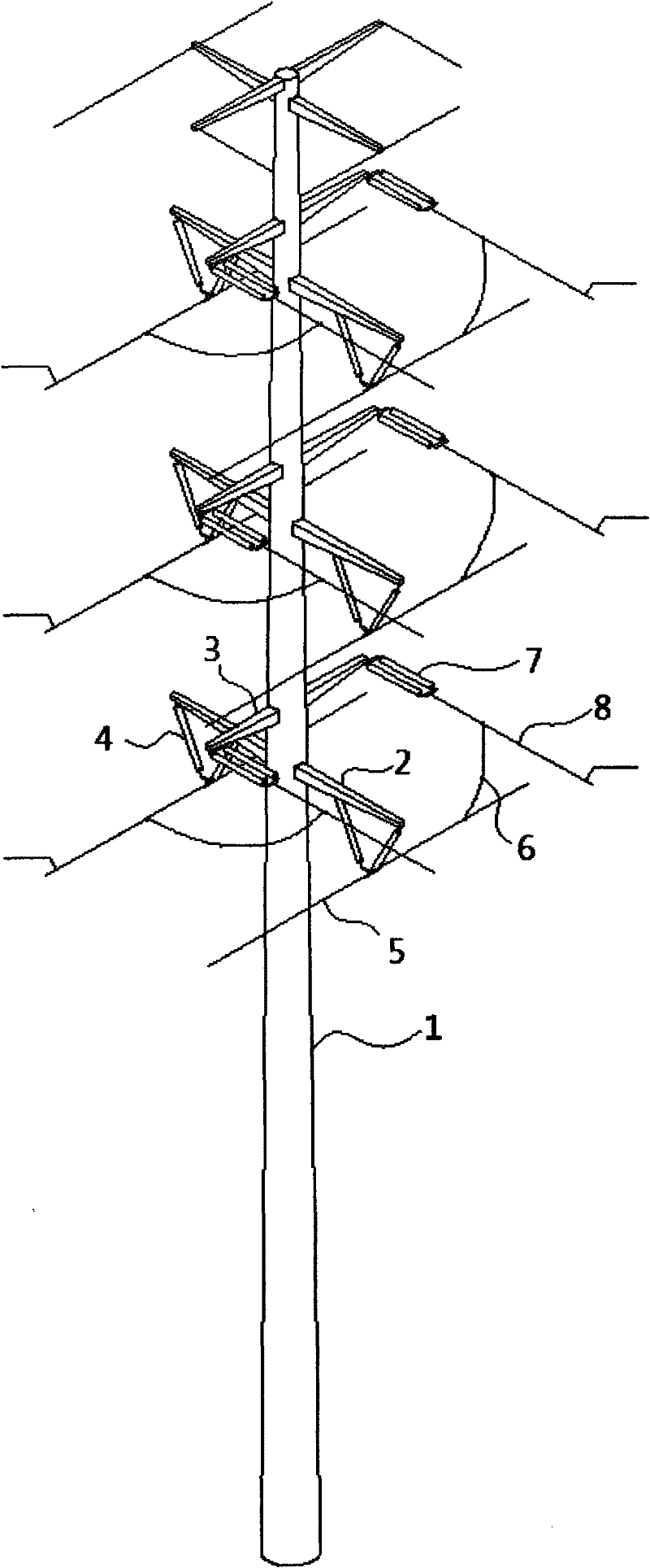
[0026] see figure 1 As shown, a steel pipe tower for a power transmission line includes a steel pipe tower trunk 1, a plurality of branch line cross arms 3 are arranged on the steel pipe tower trunk 1, and the tail ends of the branch line cross arms 3 are connected to branch lines 8 through tension clamps 7, The steel pipe tower trunk 1 is also provided with a main line cross arm 2, the main line cross arm 2 and the branch line cross arm 3 are arranged alternately, and the arm of the main line cross arm 2 is connected with a suspension line for suspending the main line 5 Clip 4.

[0027] Preferably, a pair of suspension wire clamps 4 are arranged on the arm of the main line cross arm 2, and the pair of suspension wire clamps 4 are arranged in a "V" shape.

[0028] Use the construction method of transmission line...


PUM


Abstract

The invention discloses a power transmission line steel tube tower which comprises a steel tube tower trunk, wherein multiple branch line cross arms are arranged on the steel tube tower trunk; the tail ends of the branch line cross arms are connected with branch lines through strain clamps; a mainline cross beam is also arranged on the steel tube tower trunk; the mainline cross beam and the branch line cross beams are arranged in a staggered manner; and arm of the mainline cross arm is connected with a suspension clamp for suspending the mainline. Through the power transmission line steel tube tower disclosed by the invention, external power-cut time is short in construction; the line hardware materials are few; the construction personnel and labor amount are reduced; and equipment used at site is reduced.

Description

technical field [0001] The invention relates to a steel pipe tower for transmission lines. Background technique [0002] At present, the steel pipe tower of the conventional transmission line is composed of the steel pipe tower trunk and several branch line cross-arms arranged on the trunk. The general specific implementation steps of the connection of the main line are as follows: [0003] 1. To anchor the conductors in the front and rear trunks, 12 Φ16 steel wire ropes need to be clamped with clamps, and the conductors are anchored on the ground anchors; [0004] 2. Pull the wire with a motorized winch, then break the wire and loosen it to the ground; [0005] 3. Make hydraulic connection tension clamp; [0006] 4. Tighten the line, hang the line, remove the anchor line, steel wire rope, etc.; [0007] 5. Make jumper connection; [0008] The manpower and material resources required are roughly as follows: [0009] There are 16 workers, 2 motorized winch mills, 2 tens...

Claims


Application Information

Patent Timeline
IPC IPC(8): E04H12/08E04H12/24H02G7/20
Inventor 钮铁军
Owner 江苏省电力公司吴江市供电公司
Learn More