Feed-forward type microwave antenna

A microwave antenna and feed-forward technology, applied in antennas, electrical components, etc., can solve problems such as the difficulty of manufacturing large-scale CNC machine tools, the difficulty of making metal paraboloids, and energy loss, so as to improve the range of short-distance radiation, improve convergence performance, and avoid The effect of the reduction of electromagnetic energy

Active Publication Date: 2012-05-30
KUANG CHI INST OF ADVANCED TECH
View PDF5 Cites 16 Cited by
  • Summary
  • Abstract
  • Description
  • Claims
  • Application Information

AI Technical Summary

Problems solved by technology

[0003] However, the existing feed-forward microwave antenna has the following disadvantages: first, the electromagnetic wave reflected from the metal paraboloid will be blocked by the radiation source, resulting in a certain energy loss; second, the metal paraboloid is difficult to manufacture and the cost is high
This method cuts very accurately, but it is difficult to manufacture such a large CNC machine tool, and the cost is relatively high

Method used


Image

  • Feed-forward type microwave antenna
  • Feed-forward type microwave antenna
  • Feed-forward type microwave antenna

Examples


Embodiment Construction

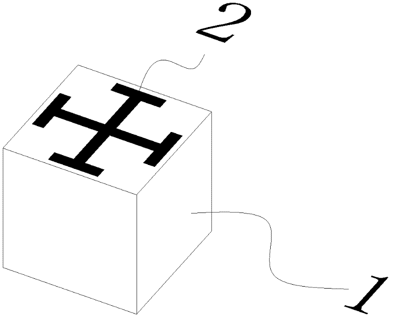
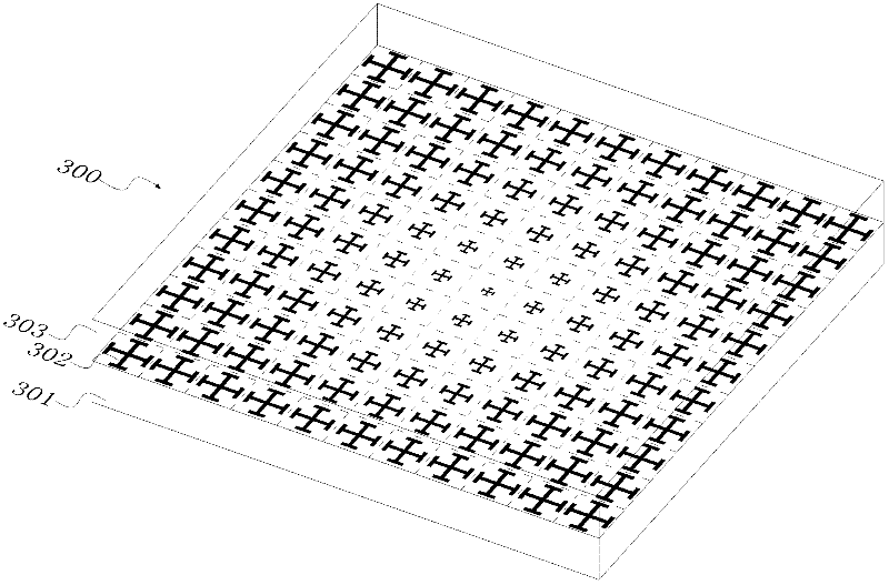
[0030]Light, as a kind of electromagnetic wave, when it passes through glass, because the wavelength of light is much larger than the size of atoms, we can use the overall parameters of the glass, such as the refractive index, rather than the detailed parameters of the atoms that make up the glass to describe The response of glass to light. Correspondingly, when studying the response of materials to other electromagnetic waves, the response of any structure in the material whose scale is much smaller than the wavelength of the electromagnetic wave to electromagnetic waves can also be described by the overall parameters of the material, such as the dielectric constant ε and magnetic permeability μ. By designing the structure of each point of the material, the dielectric constant and magnetic permeability of each point of the material are the same or different, so that the overall dielectric constant and magnetic permeability of the material are arranged in a certain order, and t...


PUM


Abstract

The invention discloses a feed-forward type microwave antenna, which comprises a radiation source, a first metamaterial panel, a second metamaterial panel and a reflection panel, wherein the first metamaterial panel and the second metamaterial panel are used for diffusing electromagnetic waves emitted by the radiation source; and the reflection panel is stuck at the back of the second metamaterial panel. After being diffused through the first metamaterial panel, the electromagnetic waves enter the second metamaterial panel to be refracted. After being reflected by the reflection panel, the electromagnetic waves enter the second metamaterial panel again to be refracted and finally exit in parallel. The antenna is manufactured by adopting a metamaterial principle; therefore, the antenna is free from limitation of the conventional shapes of a convex shape, a concave lens shape and a parabolic shape; by adopting the antenna disclosed by the invention, the shape of the antenna is planar orin any shape; furthermore, the antenna is thinner in thickness, smaller in volume and more convenient to process and manufacture; and the antenna has the benefits of being low in cost and good in gain effect.

Description

technical field [0001] The present invention relates to the field of antennas, in particular to a feedforward microwave antenna. Background technique [0002] Existing feed-forward microwave antennas usually consist of a metal paraboloid and a radiation source located at the focus of the metal parabola. The function of the metal parabola is to reflect external electromagnetic waves to the radiation source or to reflect electromagnetic waves emitted by the radiation source. The area of ​​the metal paraboloid and the machining accuracy of the metal paraboloid directly determine the parameters of the microwave antenna, such as gain and directivity. [0003] However, the existing feed-forward microwave antenna has the following disadvantages: first, the electromagnetic wave reflected from the metal paraboloid will be blocked by the radiation source, resulting in a certain energy loss; second, the metal paraboloid is difficult to manufacture and the cost is high. Metal paraboloi...

Claims


Application Information

Patent Timeline
Patent Type & Authority Applications(China)
IPC IPC(8): H01Q15/00H01Q15/23H01Q19/06H01Q19/10
Inventor 刘若鹏季春霖岳玉涛尹小明
Owner KUANG CHI INST OF ADVANCED TECH
Why Eureka
Try Eureka