
A metamaterial antenna

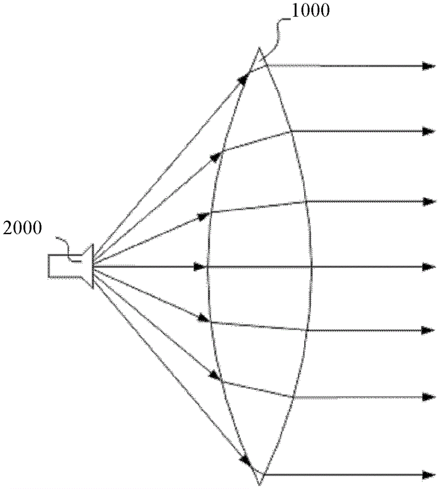
A metamaterial and antenna technology, applied in antennas, electrical components, etc., can solve the problems of limiting electromagnetic wave radiation range, unfavorable equipment miniaturization, affecting antenna size, etc., to enhance transmission distance, improve short-range radiation range, and improve antenna performance. Effect

Active Publication Date: 2016-06-29
KUANG CHI INST OF ADVANCED TECH +1
View PDF3 Cites 0 Cited by
  • Summary
  • Abstract
  • Description
  • Claims
  • Application Information

AI Technical Summary

Problems solved by technology

However, the convex lens still needs to manufacture a curved surface with uneven thickness to achieve the desired effect, and the thickness of the convex lens is relatively thick, which is not conducive to the trend of miniaturization of existing equipment
Moreover, the horn mouth of the current horn antenna limits the radiation range of electromagnetic waves to a certain extent, and also affects the size of the antenna.

Method used


Image

  • A metamaterial antenna
  • A metamaterial antenna
  • A metamaterial antenna

Examples


Embodiment Construction

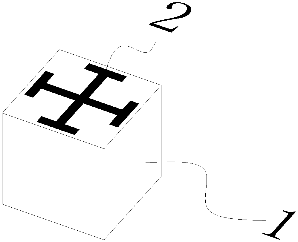
[0027] Light, as a kind of electromagnetic wave, when passing through glass, because the wavelength of the light is much larger than the size of the atom, we can use the overall parameters of the glass, such as the refractive index, rather than the detailed parameters of the atoms that make up the glass. The response of glass to light. Correspondingly, when studying the response of a material to other electromagnetic waves, the response of any structure in the material that is much smaller than the wavelength of the electromagnetic wave to electromagnetic waves can also be described by the overall parameters of the material, such as the dielectric constant ε and the magnetic permeability μ. By designing the structure of each point of the material, the dielectric constant and magnetic permeability of each point of the material are the same or different, so that the overall dielectric constant and magnetic permeability of the material are arranged regularly, and the magnetic perme...


PUM


Abstract

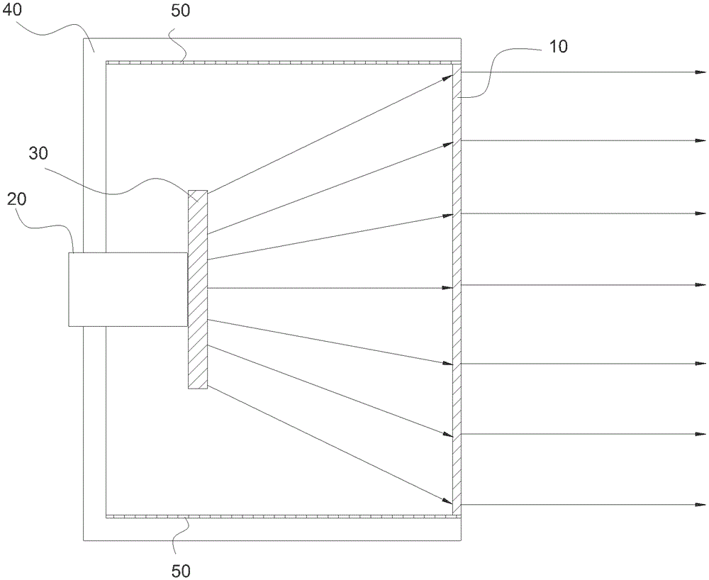
The invention relates to a metamaterial antenna. The metamaterial antenna comprises a waveguide, a first metamaterial panel tightly adhered to the waveguide and used for diverging electromagnetic waves transmitted by the waveguide, and a second metamaterial panel provided with an electromagnetic wave converging function and used for converting electromagnetic waves diverged by the first metamaterial panel into plane waves. The metamaterial antenna only needs the waveguide, does not need a horn mouth, and the divergence of the electromagnetic waves radiated out of the waveguide without limitation of the horn mouth is strong. The first metamaterial panel arranged on the waveguide enables the electromagnetic waves to be diverged, a close distance radiation range of the waveguide is widened, and the overall size of the antenna is decreased. In addition, antenna near-field energy can be adjusted according to the distribution demand of an antenna field. The electromagnetic waves transmitted by the waveguide are converted into the plane waves by designing a second metamaterial panel core layer, a second metamaterial panel gradual change layer and refractive index changes of the core layer and the gradual change layer, accordingly the converging performance of the antenna is improved, the reflection loss is reduced, and a transmission distance is prolonged.

Description

Technical field [0001] The present invention relates to the field of antennas, and more specifically, to a metamaterial antenna without a bell mouth. Background technique [0002] A horn antenna refers to an antenna whose waveguide terminal is expanded into a horn shape, and its name is derived from its shape. The horn antenna has a simple structure and easy control of the directional pattern, and can be used as a directional antenna or as a feed source. The radiation angle of the horn antenna is determined by the size of the horn. When the radiation angle needs to be enlarged, the size of the horn needs to be enlarged accordingly. In the prior art, without increasing the size of the horn, the method of expanding the radiation angle is generally to add a concave lens at the front end of the horn antenna. Due to the divergence effect of the concave lens, the radiated electromagnetic waves are diverged to expand the radiation angle. Because the curved surface of the concave lens ...

Claims


Application Information

Patent Timeline
Patent Type & Authority Patents(China)
IPC IPC(8): H01Q15/02H01Q19/06H01Q19/10
Inventor 刘若鹏季春霖岳玉涛尹小明
Owner KUANG CHI INST OF ADVANCED TECH
Learn More