Cutting device and cutting method thereof

A cutting device and cutting processing technology, applied in printing devices, printing, metal processing, etc., can solve the problems of position deviation, difficulty in ensuring the position accuracy of the cutting head and the target medium, etc.

Active Publication Date: 2012-05-30
MIMAKI ENG
View PDF7 Cites 20 Cited by
  • Summary
  • Abstract
  • Description
  • Claims
  • Application Information

AI Technical Summary

Problems solved by technology

In this way, when the target medium is fed back and forth to a large extent, it is easy to feed in a state slightly inclined with respect to the front-back direction, and positional deviation occurs, so there is a problem that it is difficult to ensure the positional accuracy of the cutting head and the target medium
[0010] Also, for example,

Method used


Image

  • Cutting device and cutting method thereof
  • Cutting device and cutting method thereof
  • Cutting device and cutting method thereof

Examples


Embodiment Construction

[0029] Embodiments of the present invention will be described below with reference to the drawings. In addition, in the following, for convenience of explanation, the arrow directions shown in each figure are respectively defined as front and rear, left and right, and up and down.

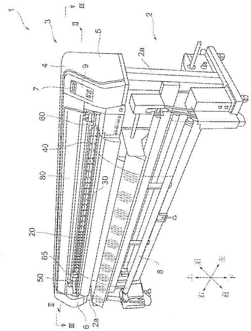
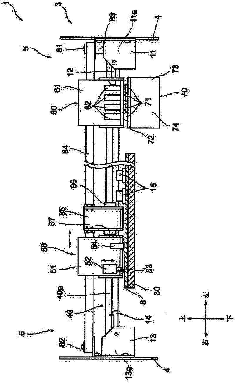
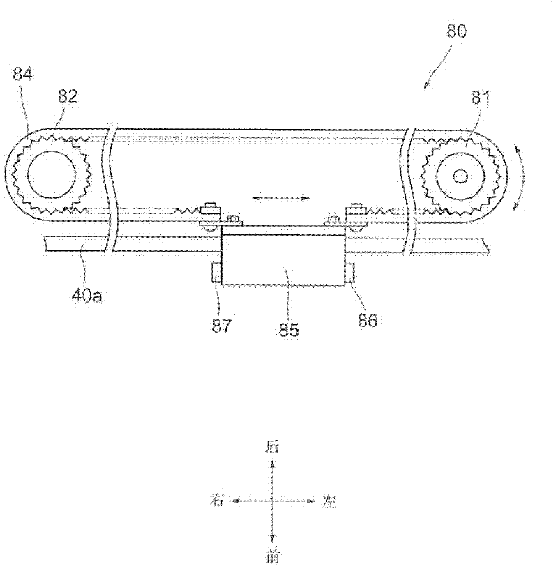
[0030] while referring to Figure 1 to Figure 5 , and the structure of the cutting device 1 to which the present invention is applied will be described. figure 1 A perspective view of the cutting device 1 is shown. figure 2 The internal structure of the main body part 3 mentioned later is shown. image 3 A plan view of a unit driving device 80 described later is shown. Figure 4 A perspective view showing the periphery of the printing unit 60 described later. Figure 5 A control system diagram of the cutting device 1 is shown.

[0031] Such as figure 1 As shown, the main body of the cutting device 1 includes: a support part 2 having a pair of left and right support legs 2a, 2a, and a main body...


PUM


Abstract

Provided is a cutting device capable of performing a cutting process under the conditions that accurate positioning between a cutting head and an object can be reliably obtained. A cutting device (1) comprises a guide rail (40a) which is opposed to a platen (30), a printer head (62) for printing an image and register marks on a sheet material (8), a cutter blade (53) for performing a cutting process to the sheet material (8), an object feeding mechanism for feeding the sheet material (8) forward and backward, a register mark detection unit (54) which detects positions of the register marks, and a controller which sets a cutting position corresponding to a print position of the image, wherein the image and the register marks are printed while the sheet material (8) is fed forward, positions of the register marks are detected by the register mark detection unit (54), and a cutting process is performed by the cutter blade (53) to the cutting position set by the controller. Before starting the cutting process, positions of the register marks printed around an image which has been printed at the rear-most side among the plurality of images, are detected, and the cutting process of the image is performed.

Description

technical field [0001] The present invention relates to a cutting device provided with a cutting head for cutting a target medium, and a cutting method using the cutting device. Background technique [0002] Conventionally, as an example of the above-mentioned cutting device, it is known to combine the operation of reciprocating the cutting head left and right and the operation of feeding the target medium back and forth with respect to the target medium supported by the platen. This is a cutting device that performs cutting processing on the target medium. On the other hand, there is also known a printer (printer) device that uses a print head (printer head) that ejects ink (ink) from ejection nozzles (nozzles) instead of the above-mentioned cutting head to print an image on the surface of a target medium. . [0003] However, in recent years, it is required to perform cutting processing corresponding to the printed image while printing the image on the target medium. In ...

Claims


Application Information

Patent Timeline
IPC IPC(8): B41J11/68B26D5/00B26D5/30
CPCB26D5/34B26D1/045B41J11/706B26D5/32B41J11/663B26F1/3806B26D5/00B26D5/30B41J11/68
Inventor 一本枪忠典西泽慎也村井厚介樋口崇
Owner MIMAKI ENG
Why Eureka
Try Eureka