Slide rail device for vehicle

A technology for slide rails and vehicles, which is applied to special positions of vehicles, vehicle seats, vehicle components, etc., and can solve problems such as unsatisfactory configurations

Inactive Publication Date: 2012-05-30
TOYOTA BOSHOKU KK +1
View PDF5 Cites 2 Cited by
  • Summary
  • Abstract
  • Description
  • Claims
  • Application Information

AI Technical Summary

Problems solved by technology

[0006] However, since the above-mentioned opening is set on the slide rail, the opening must also be formed on the cover member by machining such as cutting. Due to the cutting, an article or the like may be caught on a part with low surface accuracy, resulting in unsatisfactory composition

Method used


Image

  • Slide rail device for vehicle
  • Slide rail device for vehicle
  • Slide rail device for vehicle

Examples


Embodiment 1

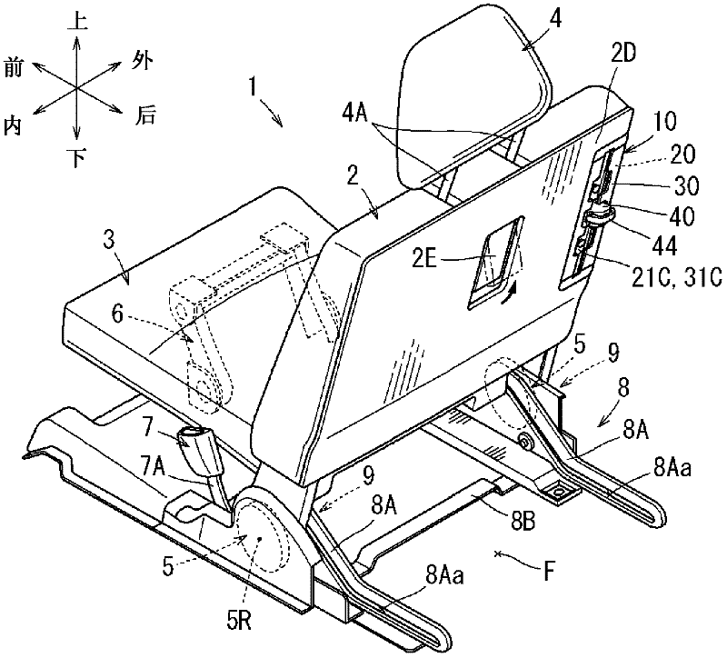
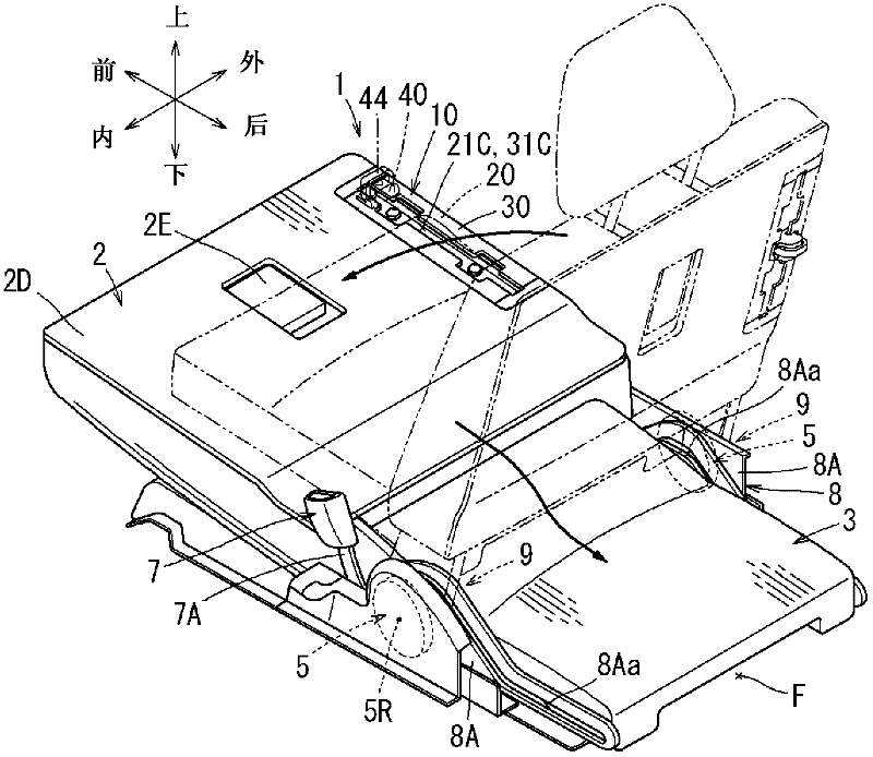
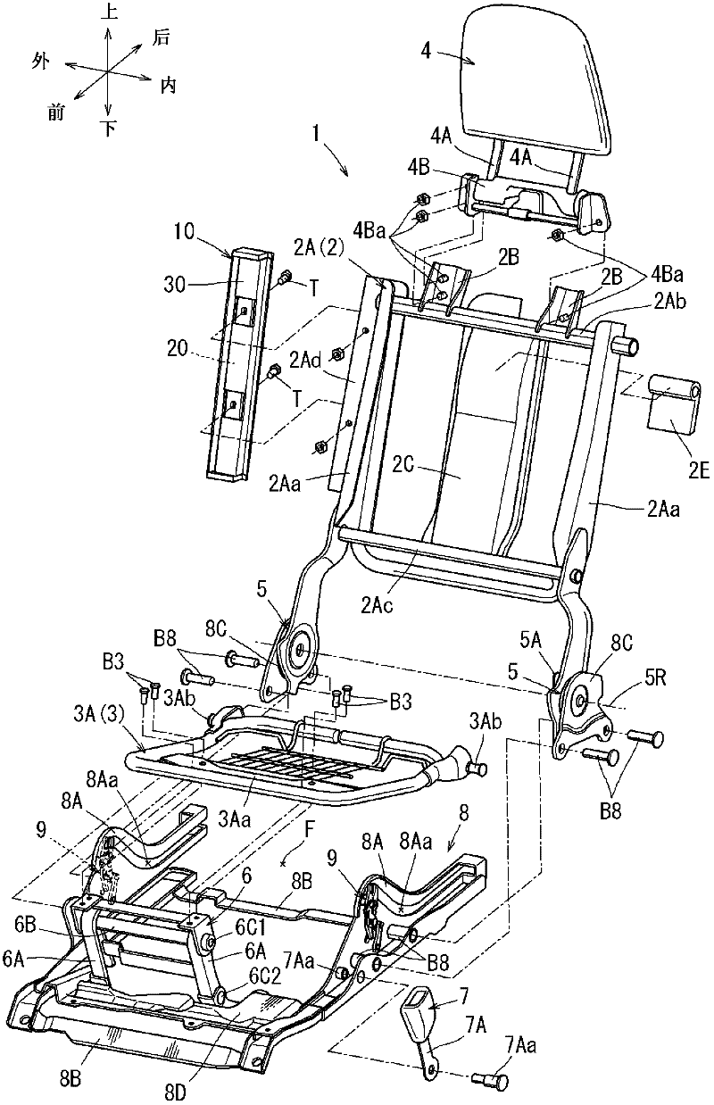
[0024] First, use Figure 1~Figure 8 The structure of the slide rail device 10 for a vehicle of Example 1 is demonstrated. here, figure 1 The structure of the vehicle seat 1 equipped with the vehicle slide rail device 10 of this embodiment is shown. The vehicle seat 1 is configured as a seat for seating on the rearmost side of a vehicle with three rows of seats (the third row of seats), and is configured to include a seat back 2 as a seat back of a seated occupant. A seat cushion 3 as a seating part and a headrest 4 for supporting the head.

[0025] Specifically, the vehicle seat 1 is a seat arranged on the right side when viewed from the rear side of the vehicle among the two left and right seats constituting the third row of seats, and is adjacent to the outer side portion facing the right side as shown in the figure. The side wall liner constituting the side wall portion of the vehicle body not shown is arranged, and the other seat (not shown) constituting the third row of se...


PUM


Abstract

An opening (21D) through which a slider (40) can be inserted into and removed from a frame of a slide rail (20) is formed in one side of the slide rail (20) in which an open slit (21C) is formed. Also, at a cover member (30), an opening (31D), the shape of which overlaps the opening (21D), is formed in a region where the opening (21D) of the slide rail (20) is formed. The opening (21D) of the slide rail (20) has an inner peripheral edge (Da) which is rounded (Da1) at a corner surface on the side opening to the outside. The inner peripheral edge (Da), the corner surface of which is rounded (Da1), is provided to protrude into the opening more inwardly than the opening (31D) of the cover member (30).

Description

Technical field [0001] The invention relates to a sliding rail device for a vehicle. Specifically, it relates to a long frame-shaped slide rail having an opening slit formed to expose a slider to the outside, and a cover member is formed on the side where the opening slit is formed. Slide rail device for vehicles. Background technique [0002] At present, there is known a structure in which a slide rail is laid on the floor of a vehicle to guide the movement of a slider provided with some functional components such as hooks. Here, the specification of U.S. Patent Application Publication No. 2007 / 0041804 discloses a structure in which a plurality of engaging teeth for slidingly locking the slider are formed on the slide rail along the longitudinal direction. In this publication, the slide rail is formed by bending a long steel plate into a rectangular frame shape in the short-side direction by press-bending it. [0003] In detail, the sliding rail has a gap formed in the mating p...

Claims


Application Information

Patent Timeline
Patent Type & Authority Applications(China)
IPC IPC(8): B60N2/06B60N2/44B60N2/90
CPCB60N2/68B60N2/01575B60N2/3013B60N2/3088B60N2/3065B60P7/0815B60N2/36B60N2/4855B60N2/856
Inventor 早原宏明井土耕平
Owner TOYOTA BOSHOKU KK
Why Eureka
Try Eureka