Indoor unit for air conditioner

A technology for indoor units and air conditioners, applied in the field of indoor units, which can solve the problems of increased forming processing costs, assembly processing costs, increased number of parts, and retention of dew condensation water, so as to reduce processing costs, reduce the number of parts, and prevent hanging Effect

Active Publication Date: 2011-07-06
MITSUBISHI ELECTRIC CORP
View PDF1 Cites 0 Cited by
  • Summary
  • Abstract
  • Description
  • Claims
  • Application Information

AI Technical Summary

Problems solved by technology

[0004] In the indoor unit of the conventional air conditioner configured as described above, since the stabilizer is formed separately from the drain pan main body, the number of parts increases, and there is a problem that the molding and assembly costs increase.
In addition, there is a problem that high-humidity air infiltrates from the fitting part of the drain pan and the stabilizer into the space formed by the drain pan and the stabilizer, and condensation water stays inside.
In addition, when operating in a state where the blown air volume is small, the external air flows backward along the air duct side of the bottom surface of the drain pan, and there is also the problem that the fan is prone to exposure.

Method used


Image

  • Indoor unit for air conditioner
  • Indoor unit for air conditioner
  • Indoor unit for air conditioner

Examples


Embodiment 4

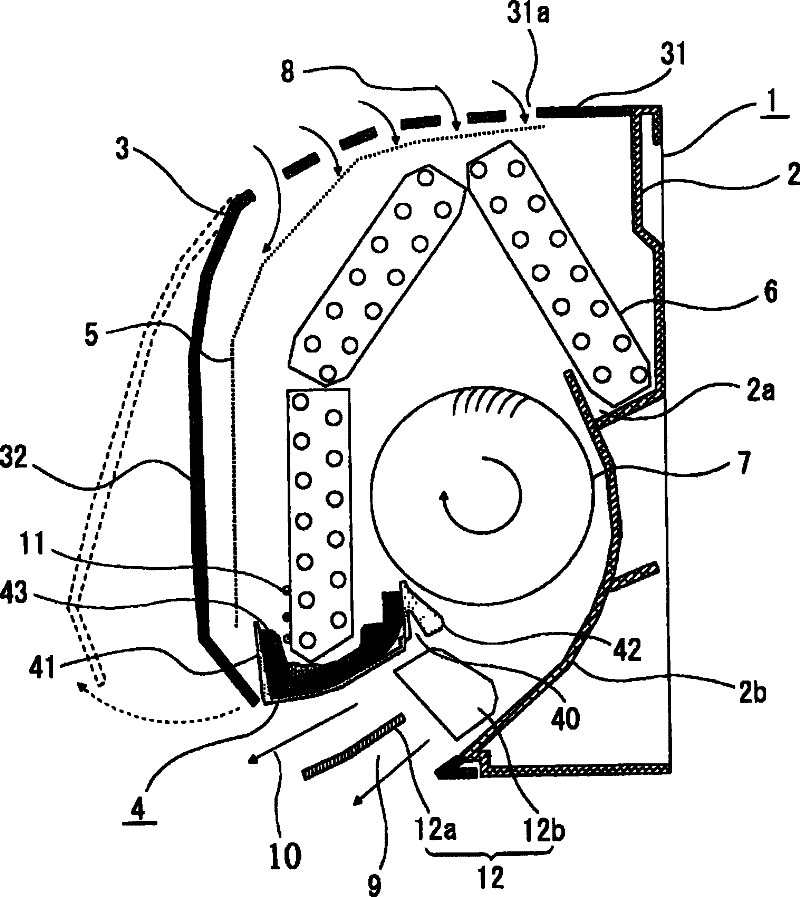
[0038] In this Embodiment 4, the material of the above-mentioned heat insulating member 43, which is not shown in the drawing, may be made of impact-resistant polystyrene (high-impact polystyrene), polyethylene, polypropylene, or their copolymers. The same material (illustration omitted) of the indoor unit is obtained as in the above-described first embodiment. Since it is the same as Embodiments 1 to 3 except that the material is changed, refer to figure 1 Be explained.

[0039] According to the configuration of the fourth embodiment, when the respective components are assembled to figure 1 In the case of the indoor cabinet 1 shown, since the thermal insulation member 43 has excellent impact resistance, cracking and chipping of the thermal insulation member 43 due to contact with the lower end portion 6a of the heat exchanger 6 can be suppressed, and process failures can be reduced. For this reason, an effect of improving production efficiency can be obtained.


PUM


Abstract

An indoor unit for an air conditioner, in which a heat exchanger, a blower, and a drain pan are received inside an indoor unit housing, where the drain pan receives, below the heat exchanger, drain water condensed by the heat exchanger, and the indoor unit housing has a suction opening and a blowout opening. The rear surface of the drain pan faces an air channel continuing to the blowout opening.A stabilizer is provided at an end on the upstream side of the air channel of the drain pan. The drain pan (4) is integrally formed by cast molding and has a drain pan body (41) and a stabilizer section (42). A recess (40) is formed in a portion near and on the air channel side of the boundary between the drain pan and the stabilizer section.

Description

technical field [0001] The present invention relates to an indoor unit of an air conditioner installed on a wall surface of a room and used. Background technique [0002] As an indoor unit of a conventional air conditioner, there is an indoor unit having such a structure (for example, refer to Patent Document 1) in which a drain pan for recovering dew condensation water generated by a heat exchanger and a drain pan provided in the drain pan are provided. The stabilizers on the upstream side of the air duct (the part closest to the cross-flow fan) are configured separately, and the stabilizers are fitted to the end of the drain pan and fixed. [0003] Patent Document 1: Japanese Patent No. 3107504 (page 1, figure 1 ) [0004] In the indoor unit of the conventional air conditioner configured as described above, since the stabilizer is formed separately from the drain pan body, the number of parts increases, and there is a problem that the cost of molding and assembly increas...

Claims


Application Information

Patent Timeline
Patent Type & Authority Patents(China)
IPC IPC(8): F24F13/08F24F1/00F24F13/22
CPCF24F13/222F24F2001/0048F24F1/0011F24F1/0057
Inventor 宫本照雄代田光宏冈野勋元冈诚裕田泽哲也中畑晋介河原洋平
Owner MITSUBISHI ELECTRIC CORP
Why Eureka
Try Eureka