
Flange joint

A flange joint and flange technology, applied in the direction of flange connection, pipe/pipe joint/pipe fitting, through components, etc., can solve the problems affecting railway transportation safety, leakage and leakage of sealing rings and joint bodies, and achieve automatic Compensate for sealing effect, improve reliability, reasonable structure effect

Active Publication Date: 2014-01-01
CRRC SHANDONG CO LTD
View PDF5 Cites 1 Cited by
  • Summary
  • Abstract
  • Description
  • Claims
  • Application Information

AI Technical Summary

Problems solved by technology

Once the seal of the joint fails during use, it will cause leakage. For example, the air brake piping system of the railway wagon running on the line in our country is affected by the installation, use and maintenance. Leakage is common, especially in the cold areas of our country. Problems that cannot be solved for a long time have seriously affected the safety of railway transportation
[0003] The patent application number is 200820062412.8, the announcement number is CN201162820Y, and the announcement date is December 10, 2008. The name is "elastic sealing ring" and discloses a sealing ring. image 3 , 4 , 5 discloses the structure of the flange joint, the deficiency of its technical scheme is: when the installation conditions meet the design requirements, after the "E" shaped sealing ring is installed in the corresponding part of the flange, because the joint body is rigidly connected, the sealing ring Compacted, the "E" ring is compressed, forming a "rectangular" rubber gasket
When there is a gap in the sealing due to installation problems, deformation of the flange body or loosening of the fastening bolts, the pressure gas enters the gap between the two joint bodies, but cannot enter the ventilation groove, so the pressure air can only exert pressure on the upper lip , so that there is a gap between the sealing ring and the joint body and a large amount of leakage occurs. It can be seen that the leakage of the flange joint is mainly caused by the unreasonable design of the sealing ring and the joint body.

Method used


Image

  • Flange joint
  • Flange joint
  • Flange joint

Examples


Embodiment Construction

[0034] The present invention will be described in further detail below in conjunction with the accompanying drawings, but it should not be understood that the scope of the above subject of the present invention is limited to the following embodiments.

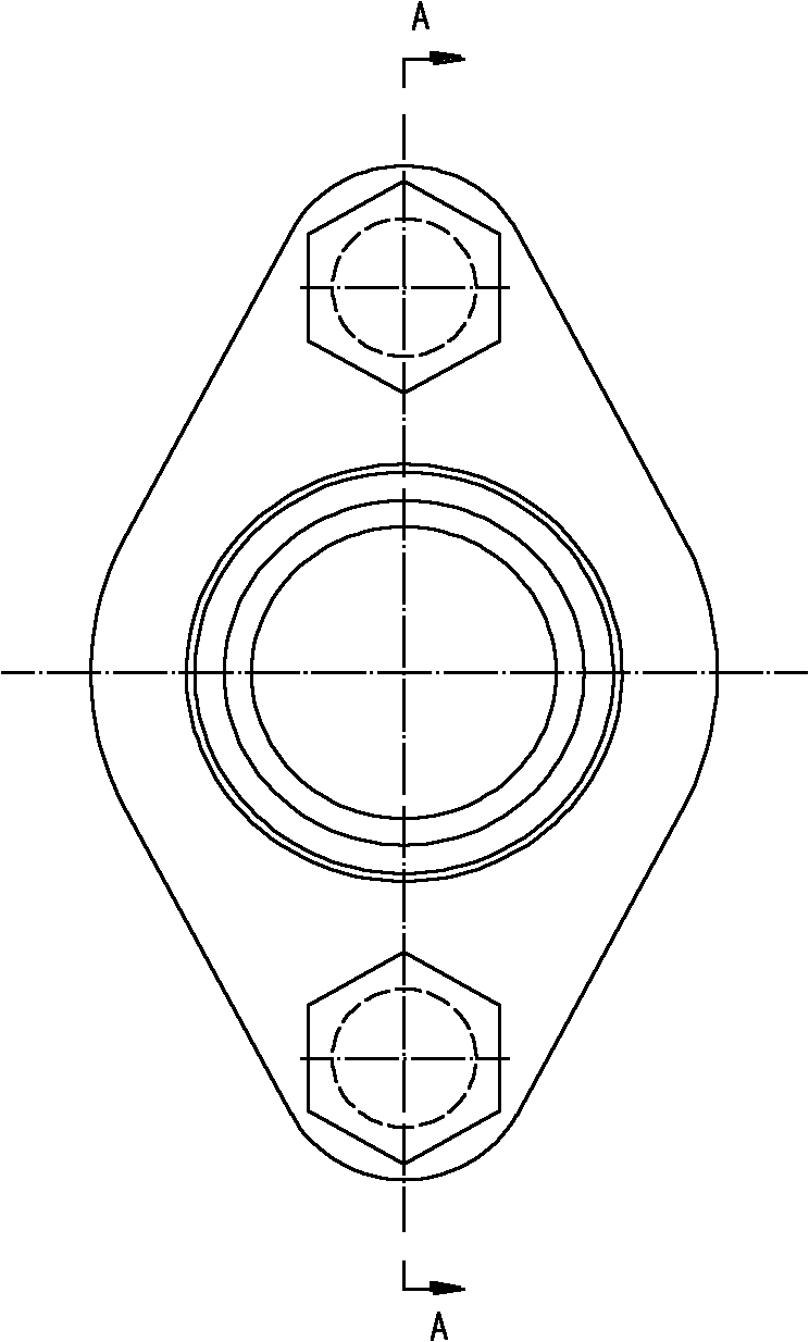
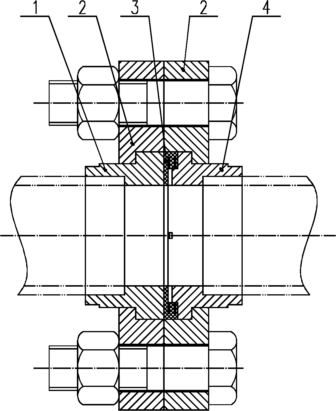
[0035] Such as figure 1 , figure 2 As shown, the flange joint includes two joint bodies: joint body I1 and joint body II4 respectively, two flange bodies 2, sealing ring (rubber sealing ring 3) and bolts and nuts for fixing the two flange bodies 2 .

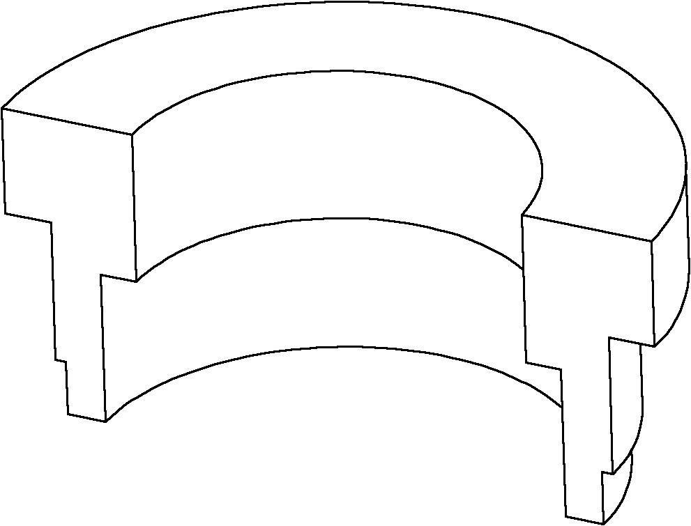
[0036] Such as image 3 As shown, the joint body I 1: there is a circular hole in the middle of the axial direction, and a boss is provided in the outer circumferential direction, and the boss is close to its respective end face, and the opposite end face of the joint body is a smooth plane; the circular hole is axially in the middle The inner side away from the end face is provided with a groove for installing the pipe, so that the section of the circular hole along the axial...


PUM


Abstract

The invention discloses a flange joint, which comprises two joint bodies, two flange bodies and a seal ring, wherein the end faces of the two joint bodies are opposite; a circular hole is arranged at the middle in the axial direction of each joint body; a boss is arranged in the direction of the outer circumference of the joint body; the bosses are near the respective end faces of the two joint bodies; a ring groove is arranged between the two joint bodies; a seal element is arranged in the ring groove; the end faces of the two flange bodies are opposite; the middles of the two flange bodies are respectively provided with a circular hole; annular locking grooves matched with the bosses are arranged in the circular holes; the bosses of the two joint bodies are locked in the locking grooves of the two flange bodies; the two flange bodies are fixed together through a connecting piece; the joint bodies are provided with a plurality of vent grooves for enabling the circular holes to be communicated with the ring groove; the cross section of the seal ring is in a stepped E shape; the seal ring comprises a ring body, a big outer ring surface and a small outer ring surface; the inner side of the ring body is provided with a gap extending along the circumferential direction; the big outer ring surface and the small outer ring surface are respectively formed at both sides in the circumferential direction of the gap; and the radial width of the big outer ring surface is greater than that of the small outer ring surface. In the flange joint disclosed by the invention, when the seal dual face of the joint deforms or a fastener looses to generate an abnormal seal, under the pressure of seal gas, extending deformation is generated on a seal layer to form a new seal at the position of a sealed gap, and thereby, an effect of automatic seal compensation is achieved.

Description

technical field [0001] The invention relates to a flange joint for connecting brake air pipes of railway wagons, in particular to a joint for sealed connection of pressure gas pipelines. Background technique [0002] There are various structural forms of flange joints. Most of the joints are "passive" seals under the premise of ensuring that the sealing structure meets the requirements of design, manufacture and maintenance, that is, the necessary compression of the sealing ring in the joint must be maintained under working conditions. Rate. Once the compression rate is reduced due to installation problems or loose installation, the sealing effect of the joint will be reduced, and this phenomenon is more significant for the most difficult airtight seal. Once the seal of the joint fails during use, it will cause leakage. For example, the air brake piping system of the railway wagon running on the line in our country is affected by the installation, use and maintenance. Leaka...

Claims


Application Information

Patent Timeline
Patent Type & Authority Patents(China)
IPC IPC(8): F16L23/16F16L23/18
Inventor 吴杰刘寅华刘安全刘红日
Owner CRRC SHANDONG CO LTD
Learn More