Valve

A valve sleeve and valve core technology, applied in the field of valves, can solve problems such as the troublesome manufacturing process of the single-piece sealed shell

Inactive Publication Date: 2016-06-15
FESTO AG & CO KG
View PDF7 Cites 2 Cited by
  • Summary
  • Abstract
  • Description
  • Claims
  • Application Information

AI Technical Summary

Problems solved by technology

However, the manufacturing process of the one-piece sealed housing by material deformation becomes relatively cumbersome

Method used


Image

  • Valve
  • Valve
  • Valve

Examples


Embodiment Construction

[0033] Unless otherwise stated, the following explanations apply to all embodiments.

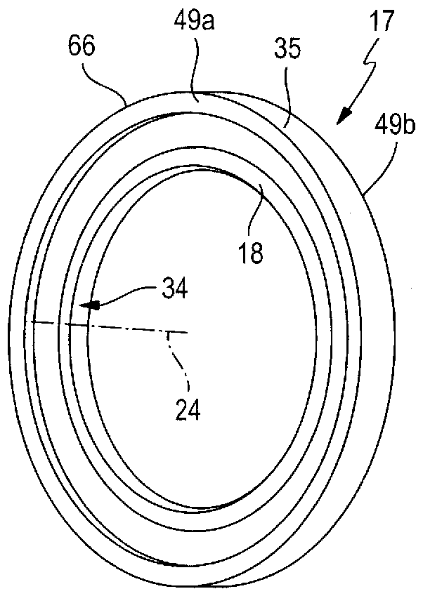
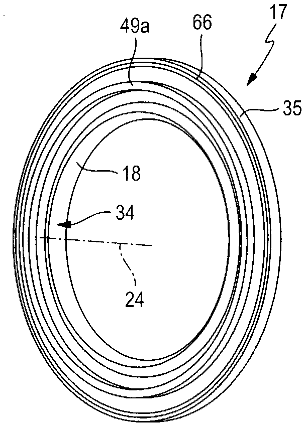
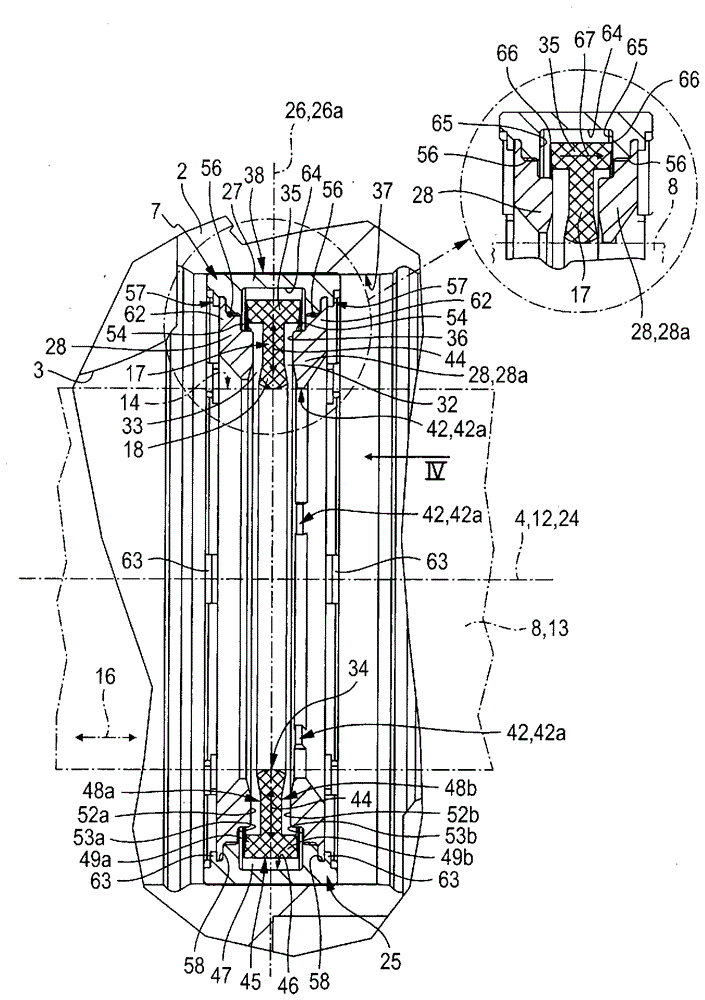
[0034] The valve indicated overall by the reference numeral 1 preferably has the design as a multi-way valve and has a valve housing 2 in which a recess 3 having a linear elongated, preferably cylindrical contour, is formed. The recess 3 has an imaginary central longitudinal axis 4 which is outlined with a dash-dotted line.

[0035] A plurality of valve channels 5 , which pass through the valve housing 2 , open into the recess 3 at locations axially spaced from one another in the periphery. Between the gap section 6 of the gap 3 that communicates with a corresponding one of the valve passages 5, a corresponding sealing ring 7 with a special structure is placed in the gap 3, and further The structure of the sealing ring is discussed. In any case, preferably a plurality of sealing rings 7 having a coaxial arrangement and an axial spacing from one another are arranged in the recess 3 .

[00...


PUM


Abstract

The invention relates to a valve (1), which has at least one seal ring (7) arranged in a recess (3) of a valve housing (2), which seal ring has a seal housing (25) having a U-shaped cross-section, in which seal housing an annular sealing element (17) is arranged. The seal housing (25) has a multi-part design and contains at least one separate housing leg (28), which is fixed to an annular bottom section (27) of the seal housing (25) in a joining region (56). The sealing element (17) has a static sealing section (35), which engages in a sealing groove (64) formed in the bottom section (27) and is suitable for interacting with the two groove flanks (65) of the sealing groove (64) in a sealing manner.

Description

technical field [0001] The invention relates to a valve with a valve sleeve (Ventilgehöuse) and a piston-shaped valve slide (Ventilschieber), which switches between different operating positions while performing a linear switching movement (Umschaltbewegung). The space between them is axially displaceable in the recess of the valve sleeve with a central longitudinal axis, and the valve furthermore has at least one sealing ring coaxially enclosing the valve core in the recess, the sealing ring Having a U-shaped cross-section and two opposite housing legs (Gehöuseschenkel) connected to each other by a radially outer annular base section results in a fixed position relative to the valve sleeve. Fixed multi-part annular sealing housing, wherein at least one housing arm of the two housing arms is configured separately with respect to the bottom section and fixed in the joint region on the The body at the bottom section, wherein the sealing housing encloses a receiving chamber whic...

Claims


Application Information

Patent Timeline
Patent Type & Authority Applications(China)
IPC IPC(8): F16K11/07F15B13/04
CPCF16K11/0712Y10T137/86694F16J15/3252F16K1/44
Inventor M.贝尔纳F.雷普克
Owner FESTO AG & CO KG
Why Eureka
Try Eureka