Water tank device for water pressurizing flushing closet

A flush toilet, pressurized water technology, applied in water supply devices, flushing equipment with water tanks, water resource protection, etc., can solve the problem of limited flushing speed, and achieve the effects of reducing pressure, facilitating installation, and saving water resources

Inactive Publication Date: 2004-11-17
林莉
View PDF0 Cites 0 Cited by
  • Summary
  • Abstract
  • Description
  • Claims
  • Application Information

AI Technical Summary

Problems solved by technology

Due to the limited drop, the speed of flushing is also

Method used


Image

  • Water tank device for water pressurizing flushing closet
  • Water tank device for water pressurizing flushing closet
  • Water tank device for water pressurizing flushing closet

Examples


Embodiment Construction

[0014] The present invention will be further described below in conjunction with the accompanying drawings and embodiments.

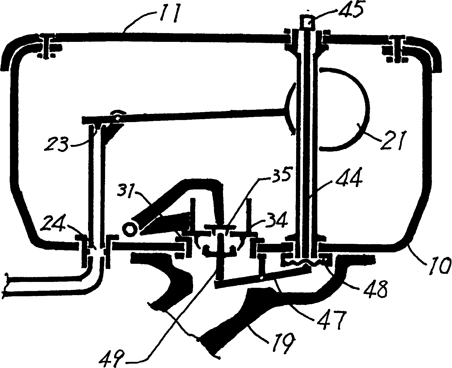
[0015] exist figure 1 In the embodiment, the water tank body 10 that has sealed water tank cover 11 is a closed container; The structure of the water inlet valve assembly including the float 21 in the figure and the structure of the water inlet pipe 24 are the same as the common flush toilet. When the water tank 10 was filled with water, the water inlet valve 23 was opened, and the inner ring 35 and the outer ring 34 of the flush valve were automatically closed. Since the water tank 10 was closed, the water intake continuously compressed the air in the water tank. During a certain height, the floating ball 21 closes the water inlet valve 23, and the water inlet process ends; at this moment, the air in the water tank is compressed, and the pressure of the compressed air on the water surface in the water tank is greater than the common atmospheric pressur...


PUM


Abstract

The present invention relates to a kind of cistern device for flushing closet and the cistern is one closed container. The pressure of incoming water is utilized to produce compressed air in the cistern, so that water under the action of both its own gravity and compressed air inside the cistern can flush toilet with relatively high speed and thus less water consumption. Compared with available common cistern, the present invention can save water without additional power consumption.

Description

technical field [0001] The invention relates to a water tank device of a flush toilet. Background technique [0002] The flush toilet currently used mainly relies on the drop between the water level in the water tank and the water level in the urinal to generate pressure, so that the falling water has a certain speed, so as to achieve the purpose of cleaning the urinal. Due to the limited drop, the flushing speed is also limited, and more water is needed to clean the urinal. Contents of the invention [0003] The purpose of the present invention is to use compressed air to increase the flushing speed, reduce the water consumption of the flush toilet, save water resources, and at the same time, enable the user to operate the flushing of the flush toilet conveniently and labor-savingly, and invent a water tank for a pressurized flush toilet device. [0004] The technical solution adopted by the present inven...

Claims


Application Information

Patent Timeline
IPC IPC(8): E03D1/14E03D3/10
CPCY02A20/40
Inventor 林莉
Owner 林莉
Why Eureka
Try Eureka