Heat transfer structure, its manufacturing method and its heat dissipation method

A technology of manufacturing method and heat dissipation method, which is applied in semiconductor/solid-state device manufacturing, electrical components, electric solid-state devices, etc., can solve the problems of affecting the heat dissipation effect, large thermal expansion coefficient, and no metal heat-conducting layer, etc., and achieve the goal of improving the blocking phenomenon Effect

Inactive Publication Date: 2018-03-20
FAR EAST UNIVERSITY
View PDF5 Cites 0 Cited by
  • Summary
  • Abstract
  • Description
  • Claims
  • Application Information

AI Technical Summary

Problems solved by technology

However, the metal heat conduction layer between the heat source and the heat dissipation thin plate, because of its large thermal expansion coefficient, is prone to dramatic volume changes with the change of the heat source temperature, resulting in serious cracks that affect the heat dissipation effect, so the metal heat conduction layer has no It is widely used as the heat conduction medium between the heat source and the thin plate for heat dissipation

Method used


Image

  • Heat transfer structure, its manufacturing method and its heat dissipation method
  • Heat transfer structure, its manufacturing method and its heat dissipation method
  • Heat transfer structure, its manufacturing method and its heat dissipation method

Examples


Embodiment Construction

[0038] Based on the above technical features, the main beneficial effects of the heat transfer structure, its manufacturing method and heat dissipation method of the present invention can be clearly presented in the following embodiments.

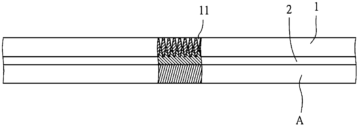
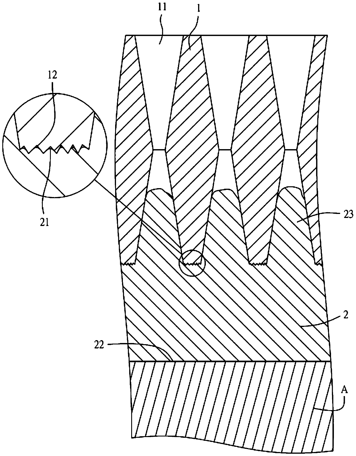
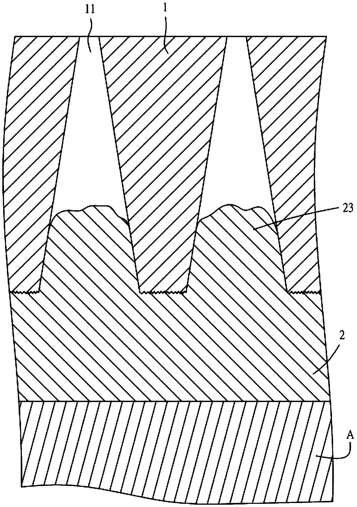
[0039] Please refer to the first embodiment of the heat transfer structure of the present invention figure 1 and figure 2 As shown, it includes: a microporous plate 1 with a plurality of through-holes 11 that can generate capillary action, the diameter of the through-holes 11 is between 10 microns and 90 microns, and the cross-section of the through-holes 11 is an hourglass shape, and the section of the through hole 11 can also be an upright triangle (please refer to image 3 ) or other shapes, which are not limited; a metal heat-conducting layer 2 has a first contact surface 21 and a second contact surface 22, and the first contact surface 21 is used to contact a surface 12 of the microporous plate 1 , the surface 12 is a rough surface ...


PUM

PropertyMeasurementUnit
melting pointaaaaaaaaaa

Abstract

The present invention relates to a heat transfer structure, its manufacturing method and its heat dissipation method, which are used to solve the problem that known alloys used in heat dissipation components will have drastic volume changes as the temperature of the heat source changes, resulting in serious cracks and poor heat dissipation effects Shortcomings. The heat transfer structure of the present invention includes: a microporous plate; a metal heat conducting layer, which contacts the microporous plate and the heat source, and the metal heat conducting layer has a plurality of protrusions correspondingly protruding into the through holes, and combined with At the inner edge of the through hole, after the metal heat conduction layer absorbs heat, it conducts heat energy to the microporous plate through the protrusion. Therefore, the use of the metal heat conduction layer with the microporous plate can improve the influence of cracks in the heat dissipation process by increasing the heat conduction area, so that the heat transfer structure of the present invention has a good heat dissipation effect.

Description

technical field [0001] The present invention relates to a heat transfer structure, its manufacturing method and its heat dissipation method, in particular to using a metal heat conduction layer combined with a microporous plate to contact a heat source, and to strengthen the heat conduction effect of the interface through the metal heat conduction layer with good thermal conductivity, thereby Increase the heat dissipation speed of the heat source. Background technique [0002] Since the heat-generating element continuously generates heat during use, overheating may easily cause performance deterioration of the heat-generating element, such as degradation of optical characteristics or electrical characteristics. Therefore, it is necessary to dissipate the heat generated by the heat-generating element through the heat-dissipating element, and generally heat-dissipating elements use objects with heat-dissipating functions such as metal plates and heat-dissipating fins. However...

Claims


Application Information

Patent Timeline
Patent Type & Authority Patents(China)
IPC IPC(8): H01L23/367H01L21/02
Inventor 王振兴王瑜庆吴家毓
Owner FAR EAST UNIVERSITY
Why Eureka
Try Eureka