Electronic device

一种电子装置、电路板的技术,应用在电气元件、电气设备外壳/柜子/抽屉、电数字数据处理等方向,能够解决没有空间安装风扇、小散热器、大体积等问题,达到快速且均匀散逸、增加导热的面积、佳整体美观感的效果

Inactive Publication Date: 2010-06-16
JIAXING JINRISHENG TOOLS CO LTD
View PDF0 Cites 8 Cited by
  • Summary
  • Abstract
  • Description
  • Claims
  • Application Information

AI Technical Summary

Problems solved by technology

The pluggable unit 110 is usually arranged in the socket 122 of the base 120. During the operation of the electronic device 100, the pluggable unit 110 generates a lot of heat, but the volume is small, and only a small radiator can be installed. There is no space to install a fan, and the heat dissipation can only be enhanced by opening a large number of airflow inlets and airflow outlets on the chassis
However, the above method may still fail to meet the heat dissipation requirements of the electronic device 100, and the air inlet and air outlet on the surface of the casing seriously affect the overall appearance of the electronic device 100, which does not meet the customer's expectations.
In addition, because the heat dissipation specification provided by the customer must be met, the pluggable unit 110 needs a relatively large volume for the electronic device 100 if the heat dissipation requirement is to be met, which is not in line with the trend of thin, light and small electronic devices, and also goes against the electronic device 100. The original intention of multi-piece design to reduce the volume of one of the components

Method used


Image

  • Electronic device
  • Electronic device
  • Electronic device

Examples


Embodiment Construction

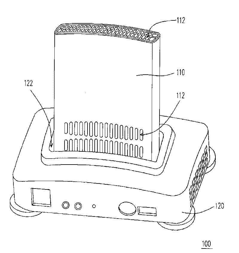
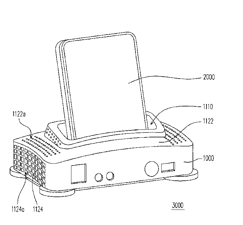
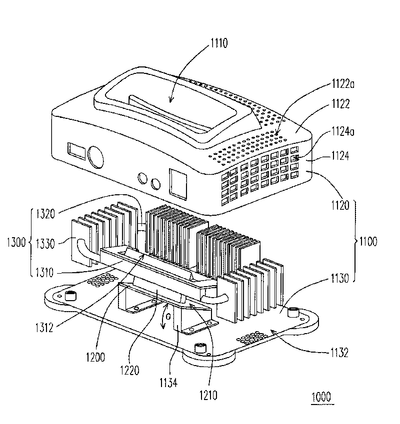
[0024] figure 2 It is a three-dimensional schematic diagram of an electronic device according to an embodiment of the present invention. image 3 shown as figure 1 exploded view of the base. Figure 4 shown as figure 1 Exploded view of the pluggable unit of . Please also refer to figure 2 , image 3 and Figure 4 , the electronic device 3000 of this embodiment includes a base 1000 and a pluggable unit 2000 . The base 1000 includes a first housing 1100, a first circuit board 1200 and a first heat sink 1300, wherein the first housing 1100 has a socket 1110, and the first circuit board 1200 and the first heat sink 1300 are disposed on the second Inside a casing 1100 . The pluggable unit 2000 can be a compact computer, which includes a second housing 2100, a second circuit board 2200 and a second radiator 2300, wherein the second circuit board 2200 and the second radiator 2300 are located on the second Inside the housing 2100 , the second circuit board 2200 has a heat s...


PUM


Abstract

The invention discloses an electronic device, comprising a base and at least a pluggable unit. The base comprises a first radiator which is provided with a first thermally conductive contact surface. The pluggable unit comprises a second shell and a heat source. A second radiator is positioned in the second shell and is provided with a second thermally conductive contact surface. When the pluggable unit is inserted into the base, the first thermally conductive contact surface is contacted with the second thermally conductive contact surface.

Description

technical field [0001] The present invention relates to a device, and more particularly to an electronic device. Background technique [0002] The heat dissipation performance inside the electronic device is very important to maintain the stable operation of the system. When the temperature inside the electronic device is too high, it may not only cause the electronic device to crash, but even cause damage to the internal electronic components in severe cases. In order to effectively reduce the heat energy generated by the operation of the electronic device and to enhance the heat dissipation effect, the usual practice is to install a relatively large heat sink inside the electronic device, and set up an air inlet and an air outlet on the casing to dissipate the hot air inside the electronic device. The heat is discharged to the outside through convection to dissipate heat. In many cases, it is necessary to install a fan inside the electronic device for forced convection he...

Claims


Application Information

Patent Timeline
Patent Type & Authority Applications(China)
IPC IPC(8): H05K5/00H05K7/20G06F1/20
CPCG06F1/1632G06F1/20G06F1/203G06F1/1626
Inventor 谷慧芳郑再魁
Owner JIAXING JINRISHENG TOOLS CO LTD
Why Eureka
Try Eureka