Drive circuit of LED light source, control circuit thereof and control method thereof

A technology of LED light source and driving circuit, applied in the field of driving electric load, can solve the problem of undesired stroboscopic, and achieve the effect of avoiding stroboscopic

Inactive Publication Date: 2012-06-27
AOTU ELECTRONICS WUHAN
View PDF6 Cites 3 Cited by
  • Summary
  • Abstract
  • Description
  • Claims
  • Application Information

AI Technical Summary

Problems solved by technology

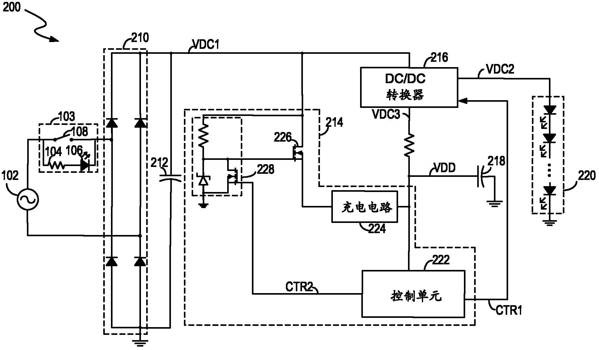
Therefore, when the switch 108 is open, the control circuit 214 is periodically enabled, so

Method used


Image

  • Drive circuit of LED light source, control circuit thereof and control method thereof
  • Drive circuit of LED light source, control circuit thereof and control method thereof
  • Drive circuit of LED light source, control circuit thereof and control method thereof

Examples


Embodiment Construction

[0020] Detailed reference will be given below to examples of the present invention. Although the present invention has been illustrated and illustrated by these embodiments, it should be noted that the present invention is not limited to these embodiments. On the contrary, the invention covers all alternatives, modifications and equivalents which are within the spirit and scope of the invention as defined by the appended claims.

[0021] In addition, in order to better illustrate the present invention, numerous specific details are given in the specific embodiments below. It will be understood by those skilled in the art that the present invention may be practiced without these specific details. In other instances, well-known methods, means, components and circuits are not described in detail so as to highlight the gist of the present invention.

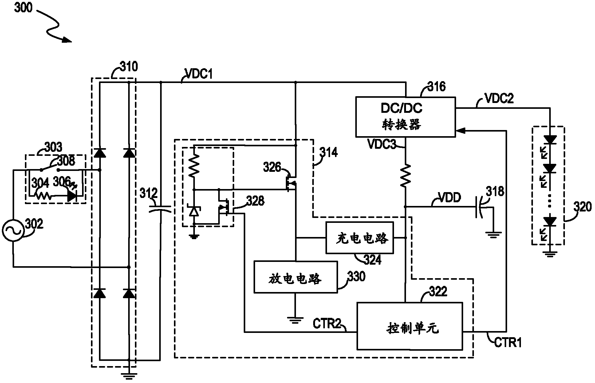
[0022] image 3 Shown is a circuit diagram of a drive circuit 300 for powering a load according to an embodiment of the present ...


PUM


Abstract

The invention discloses a drive circuit of an LED light source, a control circuit thereof and a control method thereof which are used for supplying energy to a light emitting diode (LED). The drive circuit comprises a rectifier, a filtering capacitor and a control circuit. The rectifier is used for converting alternating current voltage outputted by an alternating current power supply into rectified alternating current voltage. The filtering capacitor is coupled with the rectifier and is used for filtering the rectified alternating current voltage so as to provide direct current voltage. The control circuit is used for controlling energy supply of the LED light source. When a switch which is coupled between the alternating current power supply and the rectifier is disconnected, the control circuit enables discharge current periodically and discharges the filtering capacitor, and when the control circuit determines that the switch is in conduction, the control circuit forbids the discharge current. Through employing the drive circuit and the control method of the LED light source with a discharge circuit, when an illumination switch is disconnected, the filtering capacitor is discharged through the discharge circuit, and a stroboscopic effect of the LED source is effectively avoided.

Description

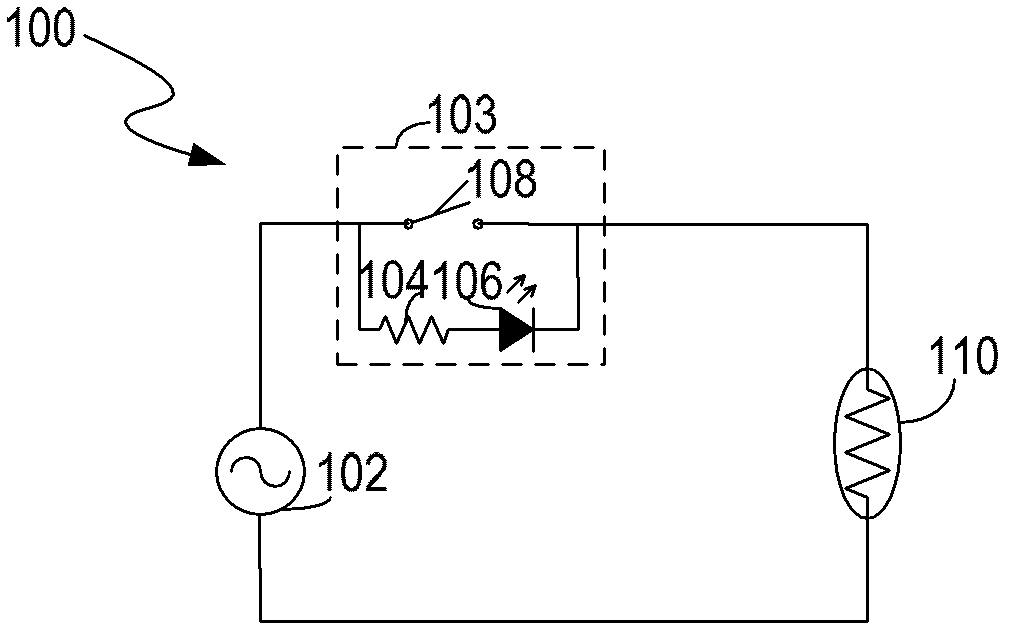
technical field [0001] The invention relates to the field of driving electric loads, in particular to a driving circuit, a control circuit and a control method for driving an LED light source. Background technique [0002] In the lighting application field, the lighting indicator light in the lighting switch is used to indicate the state of the lighting switch. figure 1 A circuit diagram of a conventional lighting circuit 100 is shown. The light switch module 103 includes a switch 108 , a current limiting resistor 104 and an indicator light 106 (such as a light emitting diode (LED). The lighting circuit 100 uses an incandescent lamp 110 as a light source. The current limiting resistor 104 is coupled in series with the indicator light 106 , and the switch 108 is coupled in parallel with the current limiting resistor 104 and the indicator light 106 . When switch 108 is open, current flows through current limiting resistor 104 , indicator light 106 and incandescent lamp 110 ...

Claims


Application Information

Patent Timeline
IPC IPC(8): H05B37/02
CPCH05B33/0815H05B37/02H05B45/3575H05B45/3725
Inventor 任智谋郭清泉阎铁生谢云宁任俊
Owner AOTU ELECTRONICS WUHAN
Why Eureka
Try Eureka