
Uphill assisting device and operation method thereof

A power-assisted device and correct position technology, which is applied in the direction of ladders, buildings, building structures, etc., can solve the problems of large volume and weight of the reel, inability to complete operations, collisions, etc.

Active Publication Date: 2014-03-05
上海和蕴机电科技有限公司
View PDF13 Cites 0 Cited by
  • Summary
  • Abstract
  • Description
  • Claims
  • Application Information

AI Technical Summary

Problems solved by technology

This technical method is called forced drive in the field of mechanical transmission; its advantage is that the linear motion of the traction rope is completely synchronized with the rotation of the main machine, but it also has the following disadvantages: the volume and weight of the reel are large, the traction rope Mutual extrusion on the barrel will lead to a reduction in service life. Before each use, the free end must be returned to the designated position. When the free end runs up and down, it is easy to interfere with, collide with, or even get stuck with the ladder and surrounding facilities due to its own swing.
Due to the need to use rope tighteners and rope knotting tools, users of the climbing assistance device cannot solve the problem immediately after discovering that the driving rope is slipping.
In fact, the work of using the rope tensioner to tighten the rope and tie the rope has a certain degree of technicality and labor intensity. Unless trained, most users of climbing assist devices cannot complete the operation

Method used


Image

  • Uphill assisting device and operation method thereof
  • Uphill assisting device and operation method thereof
  • Uphill assisting device and operation method thereof

Examples


Embodiment Construction

[0050] The embodiments of the present invention are described in detail below in conjunction with the accompanying drawings: this embodiment is implemented on the premise of the technical solution of the present invention, and detailed implementation methods and specific operating procedures are provided, but the protection scope of the present invention is not limited to the following the described embodiment.

[0051] figure 1 An embodiment of the scheme of the present invention used by climbing staff is shown. The climbing ladder 2 is fixed on the facility 1 to be climbed. Be connected to the driving rope 11 of the climbing assist device. When the climbing booster works, the driving rope 11 outputs upward boost to the climbing staff 4 through the rope clip 6 and the safety belt 5, so no matter whether the climbing staff climbs upward or downward, they can bear less load equal to the boost value. Weight, the work intensity of its climbing can be greatly reduced.

[0052] ...


PUM


Abstract

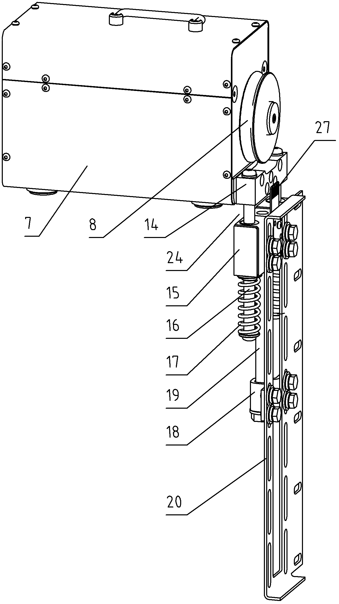
The invention provides an uphill assisting device, comprising a driving host embedded with a motor, a driving wheel and a driving wheel tension assembly; a steering wheel assembly, a driving rope and a bracket, wherein the driving host, the driving wheel and the driving wheel tension assembly are located at the lower part of a ladder stand, and the driving wheel tension assembly, the driving rope and the bracket are located at the lower part of the ladder stand; the driving rope is connected into a closed form and is used for connecting the driving wheel and the steering wheel; and the bracket is used for fixing the device on the ladder stand; the driving host is connected with the driving wheel directly or by a shaft joint, a gear, a belt and the like mechanisms; the driving wheel tension assembly comprises a driving wheel guiding block, a frame guiding block assembly, a guiding shaft, a tension mechanism and a tension frame; the frame guiding block assembly provides tension force to the driving wheel guiding block by the guiding shaft and the tension mechanism; the driving wheel and the driving wheel guiding block are arranged on the same base. The invention further provides a corresponding operation method for the uphill assisting device, according to the invention, whether the tension force of the driving rope is located at a useable range can be directly determined, if the tension force is lower than a permissive value, the tension force is adjusted to the useable range by an easy and convenient operation.

Description

technical field [0001] The invention relates to a climbing assisting device, in particular to a climbing assisting device which is suitable for providing assistance to operators in long-distance climbing occasions such as wind towers, communication towers, and chimneys, thereby reducing labor intensity. Background technique [0002] In equipment and facilities with a large height such as wind towers, communication towers, and chimneys, ladders are usually installed for staff to use up and down. In order to reduce the labor intensity of the staff, which can improve labor efficiency on the one hand, and indirectly improve safety on the other hand, some facilities have installed a booster device that is matched with the ladder and powered by a drive host that contains a motor. This device is connected to the worker's safety belt through an open-loop or closed rope, and the rope is driven by a motor to provide assistance to the worker. [0003] In the patent documents whose doc...

Claims


Application Information

Patent Timeline
Patent Type & Authority Patents(China)
IPC IPC(8): E06C7/12
Inventor 韩敏
Owner 上海和蕴机电科技有限公司
Learn More