Photosensitive drum and process cartridge

A photosensitive drum and photoreceptor technology, applied in the field of photosensitive drums, can solve problems such as affecting transmission efficiency, come out, and general products do not have suitable structures, and achieve the effect of ensuring smooth transmission and normal transmission.

Active Publication Date: 2012-07-04
江西镭博钛电子科技有限公司
View PDF6 Cites 11 Cited by
  • Summary
  • Abstract
  • Description
  • Claims
  • Application Information

AI Technical Summary

Problems solved by technology

Wherein, the end of the driving head 18 of the image forming device is provided with a triangular twisted groove 18a, and the end of the driving head 17 of the photosensitive drum is provided with a triangular non-distorted protrusion 17a correspondingly, the triangular non-distorted protrusion 17a The protrusion 17a cooperates with the above-mentioned triangular twisted groove 18a for transmission. Although this combination can realize the transmission of driving force, it is easy for the triangular non-distorted protrusion 17a to displace from the triangular twisted groove during the transmission process. 18a, thereby seriously affecting the transmission efficiency between the drive head 17 of the photosensitive drum and the drive head 18 of the image forming device
[0004] This shows that above-mentioned existing photosensitive drum and process cartridge obviously still have inconvenience and defect in structure and use, and demand urgently further improving
In order to solve the above-mentioned problems, the relevant manufacturers have tried their best to find a solution, but for a long time no suitable design has been developed, and the general product has no suitable structure to solve the above-mentioned problems. This is obviously the relevant industry. Urgent problem

Method used


Image

  • Photosensitive drum and process cartridge
  • Photosensitive drum and process cartridge
  • Photosensitive drum and process cartridge

Examples


Embodiment 1

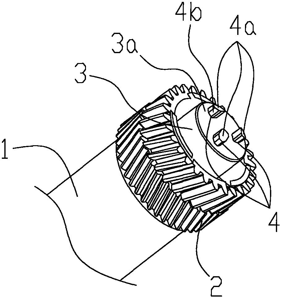
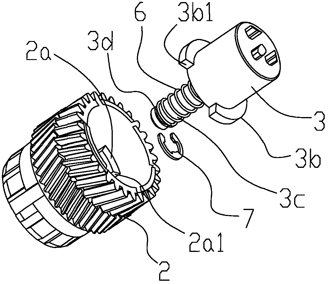
[0060] see figure 2 , image 3 and Figure 4 as shown, figure 2 is a perspective view of the drive head of the photosensitive drum according to the first embodiment of the present invention. image 3 is an exploded perspective view of the drive head at the end of the photoreceptor in the first embodiment of the present invention. Figure 4 is a sectional view of the drive head at the end of the photoreceptor in the first embodiment of the present invention. In this embodiment, the protrusion 4 is fixedly arranged on the end surface 3 a of the drum shaft 3 , and the drum shaft 3 is arranged on one end of the drum gear 2 so as to be telescopic along the axial direction of the photoreceptor 1 . Wherein, on the end of the drum shaft 3 corresponding to the drum gear 2, a power transmission part 3b and a guide column 3c are also provided, and on the drum gear 2, a power receiving part 2a and a receiving part cooperating with the power transmission part 3b are correspondingly p...

Embodiment 2

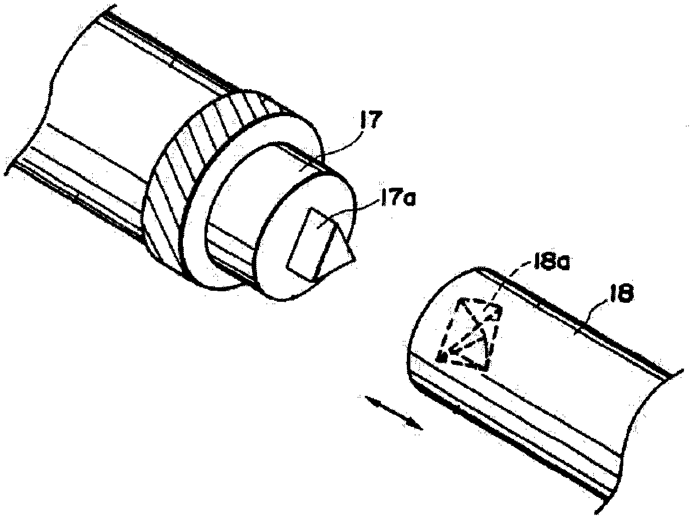
[0067] see Image 6 Shown is an exploded perspective view of the connection between the driving head of the photosensitive drum and the driving head of the image forming apparatus according to the second embodiment of the present invention. The photosensitive drum of this embodiment is basically the same as that of the first embodiment, the only difference being that in order to ensure the strength of the vertical projection 4 at the end of the photosensitive drum when it is driven between the drive head 20 of the image forming device, in this embodiment A boss 5 is also added between the three vertical projections 4 on the end face 3a of the photosensitive drum drum shaft 3 of the embodiment, and the three vertical projections 4 are arranged on the side walls of the boss 5, thereby ensuring The transmission efficiency and stability between the photosensitive drum and the image forming device.

Embodiment 3

[0069] see Figure 7 , Figure 8 as shown, Figure 7 is a perspective view of a drive head for a photosensitive drum according to a third embodiment of the present invention. Figure 8is a sectional view of the drive head at the end of the photoreceptor in the third embodiment of the present invention. The difference between the photosensitive drum of this embodiment and the first embodiment is that, in this embodiment, an opening groove 3f corresponding to the protrusion 4 is provided on the end face 3a of the drum shaft 3 of the photosensitive drum, so that the protrusion 4 is formed along the photosensitive drum. The length direction L of the body 1 is telescopically arranged in the opening groove 3 f to realize the expansion and contraction of the protrusion 4 along the length direction L of the photoreceptor 1 . The drum shaft 3 is fixedly arranged on the boss at the end of the drum gear 2 , and an accommodating space is formed between the end surface 2 d of the boss a...


PUM


Abstract

The invention relates to a photosensitive drum and a process cartridge. The photosensitive drum includes a photosensitive body, a drum gear arranged at one end of the photosensitive body, a drum shaft extending in the axial direction of the photosensitive body from an end part of the drum gear and rotationally supporting the photosensitive body, and a bulge protruding in the length direction of the photosensitive body from an end surface of the drum shaft and combined with a corresponding triangular distortion groove on a drive head of an image forming device, and further includes an elastic element, wherein the bulge is telescopically arranged at one end of the photosensitive body relative to the photosensitive body in the length direction of the photosensitive body under the action of the elastic element. Therefore, the photosensitive drum provided by the invention not only can ensure that the photosensitive drum cannot be separated out from the drive head of the image forming device when having power transmission with the drive head of the image forming device, but also can effectively ensure the stable drive power transmission between the photosensitive drum and the image forming device. Meanwhile, the invention further provides the process cartridge using the photosensitive drum.

Description

technical field [0001] The present invention relates to a photosensitive drum used in an image forming device and a process cartridge with the photosensitive drum. Background technique [0002] A process cartridge is a cartridge that can be detachably loaded into the main body of an image forming apparatus, and the cartridge as an integral unit includes an electrophotographic photosensitive assembly and components such as a charger, a developer, a cleaner, etc. at least one of the processors. Since the process cartridge is detachably mounted with respect to the main body of the image forming apparatus, maintenance of the apparatus is facilitated. The electrophotographic image forming device using the electrophotographic imaging method works like this: the charger is uniformly charged by the light of the image forming device, and the electrophotographic photosensitive component is selectively exposed to form an electrostatic latent image. The toner is developed into a toner...

Claims


Application Information

Patent Timeline
Patent Type & Authority Applications(China)
IPC IPC(8): G03G15/00G03G21/18
CPCG03G15/757G03G21/186G03G21/1671G03G21/1647
Inventor 晏梅
Owner 江西镭博钛电子科技有限公司
Why Eureka
Try Eureka