Electric pressure cooker
An electric pressure cooker and pressure technology, which is applied to pressure cookers and other directions, can solve the problems of large control error, insufficient mechanical amplification factor of rocker lever mechanism, and inability to be stably and accurately transmitted to induction devices.
- Summary
- Abstract
- Description
- Claims
- Application Information
AI Technical Summary
Problems solved by technology
Method used
Image
Examples
Embodiment 1
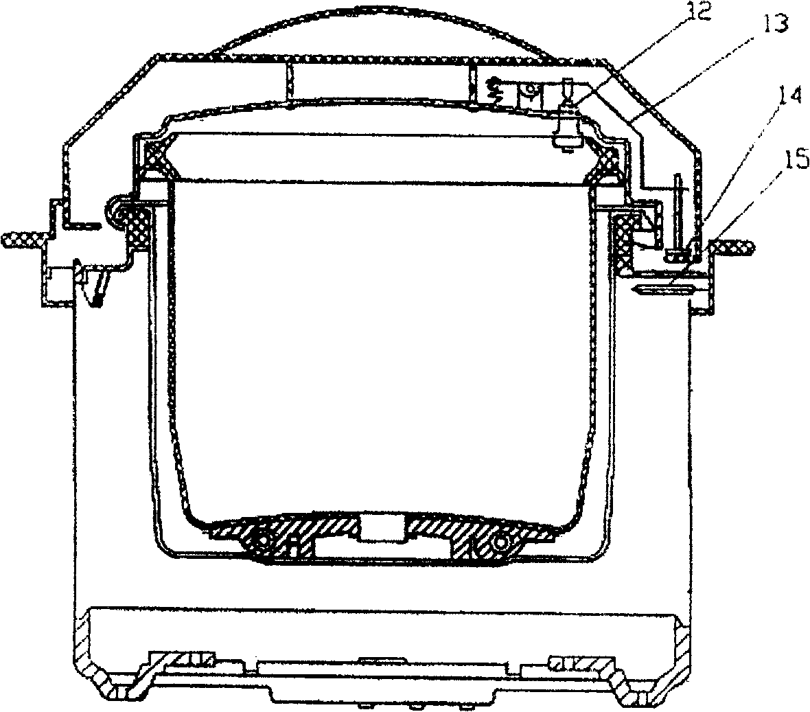
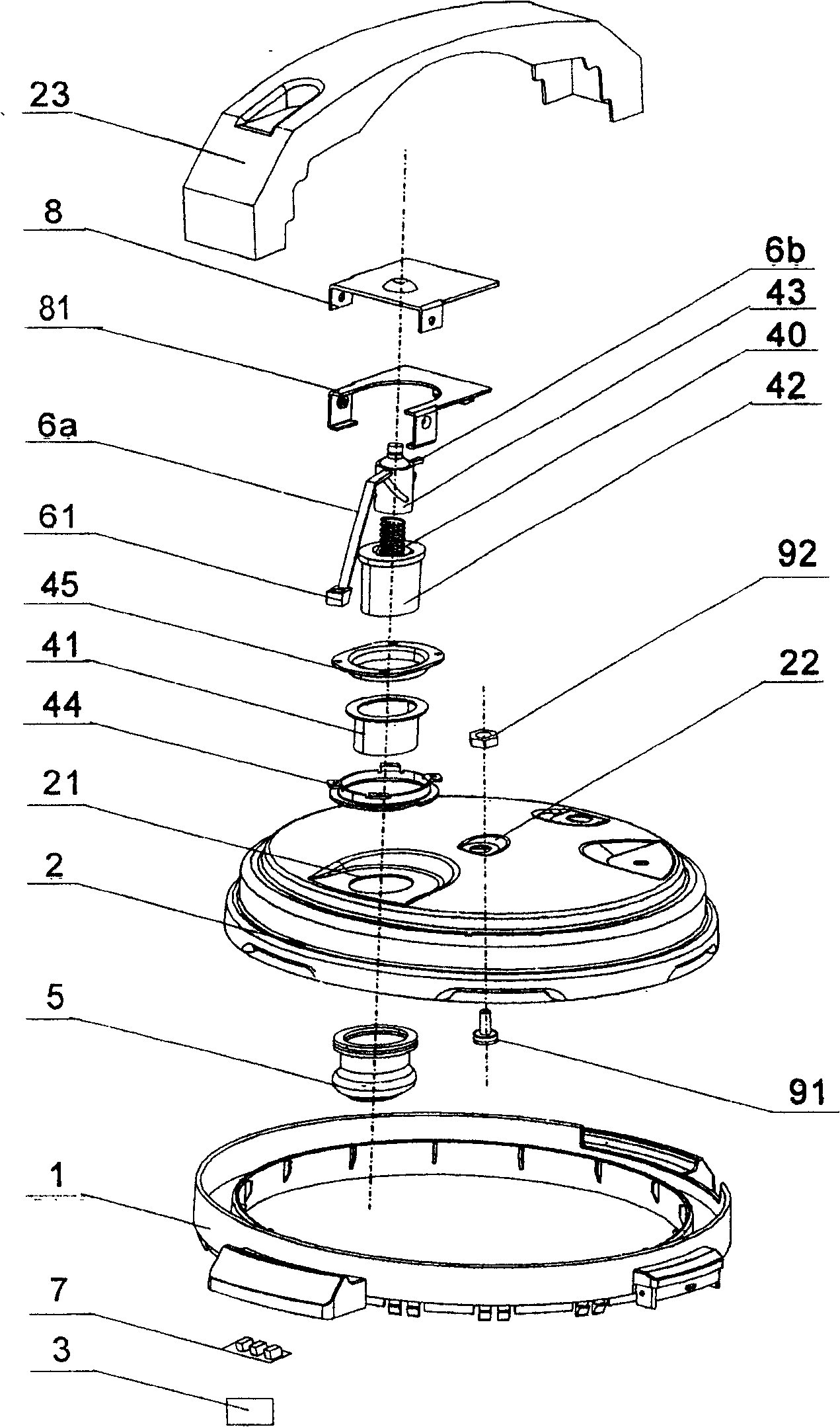
[0062] Such as figure 2 As shown, an electric pressure cooker of the present invention includes a pot body 1 and a pot cover 2 . A control circuit 3 is set in the pot body 1, and a pressure transmission device 4 and an elastic sealing sleeve 5 are set on the pot cover 2; Figure 4 As shown, the elastic sealing sleeve 5 is oval, and its lip edge 5a is fitted on the hole wall of the first hole 21 of the pot cover 2 .
[0063] The above-mentioned pressure transmission device 4 includes a bushing 41, a piston 42, and a rotating member 43, which are important parts of this embodiment. The specific structures of the bushing 41, the piston 42, and the rotating member 43 will be described in detail below.
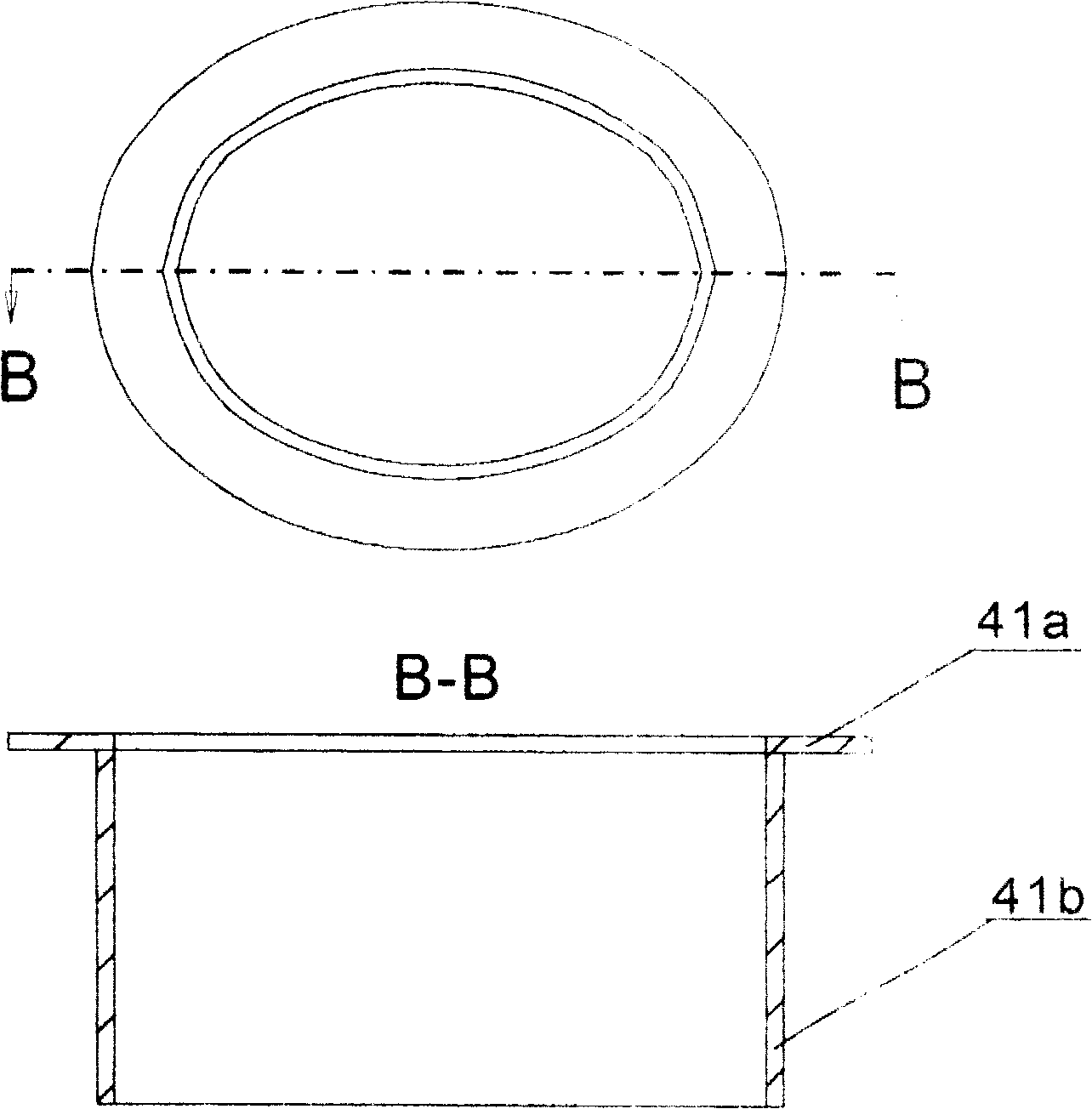
[0064] Such as image 3 and Figure 4 As shown, the bushing 41 is an elliptical body adapted to the shape and size of the elastic sealing sleeve 5 and is open up and down. The sleeve body 41b of the bushing 41 is embedded and fixed in the elastic sealing sleeve 5, so that the ...
Embodiment 2
[0074] The main difference between this embodiment and Embodiment 1 is that the structure of the pressure transmission device 4 is different. Specifically, it is the difference in the steering mechanism that realizes the conversion of linear motion into rotary motion. Such as Figure 8 and Figure 9 As shown, the outer diameter of the rotating member 43 is substantially consistent with the outer diameter of the piston 42 . Three protruding posts 42d are provided on the top edge of the piston 42; three inclined surfaces 43d corresponding to the protruding posts 42d are provided in the circumferential direction of the lower edge of the rotating member 43. Therefore, when the protruding post 42d of the piston 42 moves linearly up and down, the protruding post 42d pushes the inclined surface 43d at the lower part of the rotating member 43 to slide, thereby driving the rotating member 43 to rotate. This type of transmission is similar to toothed transmission.
PUM
 Abstract
Description
Claims
Application Information
 - R&D
- Intellectual Property
- Life Sciences
- Materials
- Tech Scout
- Unparalleled Data Quality
- Higher Quality Content
- 60% Fewer Hallucinations
Browse by: Latest US Patents, China's latest patents, Technical Efficacy Thesaurus, Application Domain, Technology Topic, Popular Technical Reports.
© 2025 PatSnap. All rights reserved.Legal|Privacy policy|Modern Slavery Act Transparency Statement|Sitemap|About US| Contact US: help@patsnap.com


