Ultrasonic anechoic imaging

An echo-free and echo-free technology, applied in the field of medical diagnostic ultrasound systems, can solve problems such as insufficient

Active Publication Date: 2012-07-04
KONINKLIJKE PHILIPS ELECTRONICS NV
View PDF5 Cites 4 Cited by
  • Summary
  • Abstract
  • Description
  • Claims
  • Application Information

AI Technical Summary

Problems solved by technology

[0007] Although this approach offers a slight improvement over its state-of-the-art, it may still be insufficient

Method used


Image

  • Ultrasonic anechoic imaging
  • Ultrasonic anechoic imaging
  • Ultrasonic anechoic imaging

Examples


Embodiment Construction

[0041] It is stated at the outset that according to the invention the word "area" refers to a position in a region of interest which is to be acquired or has been acquired but not yet converted into image data. In general, a region may refer to said location in the actual body and should be distinguished from the corresponding location in the image. Corresponding positions of regions in the image world may be defined by referring to pixels.

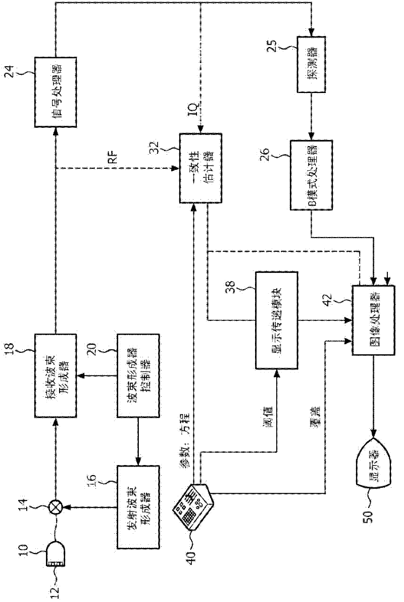
[0042] refer to figure 1 , shows an ultrasound imaging device constructed in accordance with an embodiment of the present invention. Such a device mainly comprises functional blocks known in the art and therefore will not be described in detail here, given that a person skilled in the art will recognize which obvious modifications may be made.

[0043] The device of the invention comprises an ultrasound probe 10 . This probe comprises an array transducer 12 for transmitting ultrasound signals to and receiving echo signals from a region...


PUM


Abstract

This invention relates to a method of ultrasonically imaging a region of interest that may contain anechoic and / or hypoechoic echoes. The method comprises the steps of: providing a first and a second set of ultrasound data, said two sets comprising information of the region of interest at two different instants of time respectively, determining from the first and second data sets, a temporal consistency value of at least an area of the region of interest, and producing an image indicating this area as being hypoechoic or anechoic in accordance with said temporal consistency value. Doing so, an anechoic image produced by the method of the invention emphazises the rendering of anechoic and / or hypoechoic areas over echoic ones.

Description

technical field [0001] The present invention relates to medical diagnostic ultrasound systems and methods. In particular, the present invention relates to methods for producing ultrasound images of regions of interest within the body that may contain anechoic or hypoechoic regions. The invention is particularly suitable for imaging breast cysts and vascular plaques. Background technique [0002] Breast cysts can present a diagnostic dilemma. For example, a simple cyst with a hemorrhagic content may be internally echogenic and appear suspicious on conventional ultrasound because malignant solid lesions are often hypoechoic. [0003] This dilemma can also occur when trying to determine the extent of vascular plaque. This can be challenging because many vulnerable plaques containing lipids can appear hypoechoic and resemble background blood areas inside vessels. [0004] Therefore, better visualization of hypoechoic regions on ultrasound and better differentiation between s...

Claims


Application Information

Patent Timeline
Patent Type & Authority Applications(China)
IPC IPC(8): G01S7/52G01S15/89
CPCG01S7/52036G01S7/52071G01S7/52073G01S15/8977
Inventor U·徘D·L·里士满A·V·切列帕欣杨昭文V·沙姆达莎尼
Owner KONINKLIJKE PHILIPS ELECTRONICS NV
Why Eureka
Try Eureka