
Handheld power tool, in particular power drill or power screwdriver

A technology of hand-held machine tools and auger drills, which is applied in the field of drilling rigs or auger drills, can solve the problems of increased cost, high cost, troublesome cost, etc., and achieve the effect of simple electrical coupling

Inactive Publication Date: 2012-07-11
ROBERT BOSCH GMBH
View PDF8 Cites 3 Cited by
  • Summary
  • Abstract
  • Description
  • Claims
  • Application Information

AI Technical Summary

Problems solved by technology

As a result, due to the relatively large cross-section of the drive shaft and the transmission of forces with the drive shaft due to the bearings required for supporting the drive shaft, the second housing part is relatively complex and therefore expensively constructed.
A further disadvantage is that for overlapping the distance between the battery pack arranged on the lower end of the second housing part and the switching unit, relatively long connecting cables are required, which additionally increase the electrical contacting of the hand tool machine or its drive. Difficulty or cost

Method used


Image

  • Handheld power tool, in particular power drill or power screwdriver
  • Handheld power tool, in particular power drill or power screwdriver

Examples


Embodiment Construction

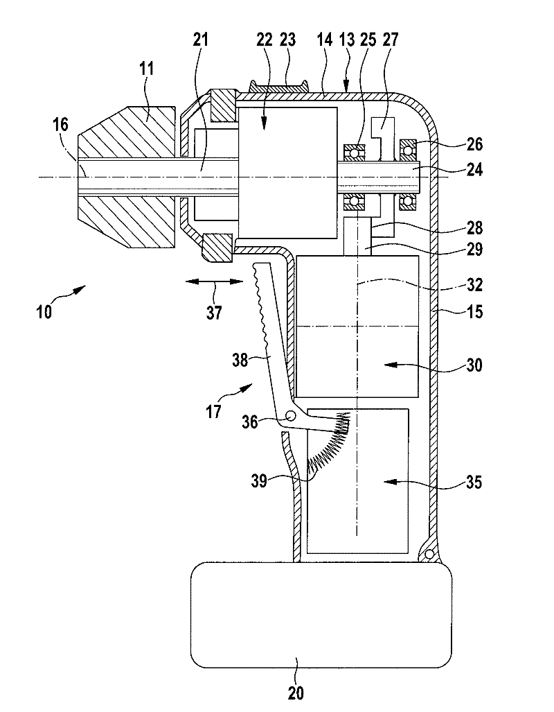
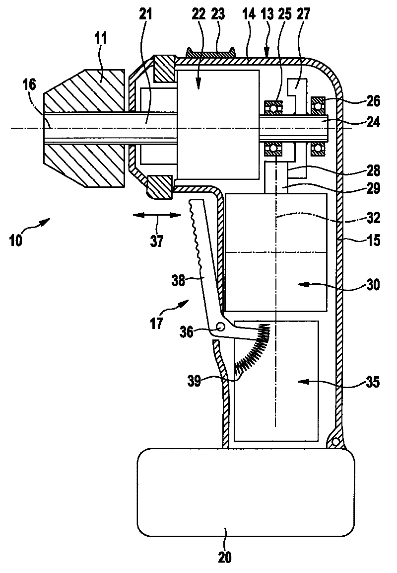
[0012] In the single figure, hand power tool 10 is shown in a very simplified manner. In this case, hand power tool 10 is formed in particular as a drill or screw drill. For this purpose, the handheld power tool 10 has a tool receptacle 11 formed by a spindle, in which a tool such as a screwdriver set or a drill can generally be clamped or locked.

[0013] The hand power tool 10 has a housing 13 , for example, consisting of two half-shells, in particular made of an injection-molded part, the parting planes of which are parallel to the plane of the drawing. The housing 13 essentially has two housing parts 14 , 15 , the first housing part 14 being aligned at least substantially in the direction of the longitudinal axis 16 of the tool receptacle 11 . The second housing part 15 of the housing 13 is arranged at least substantially perpendicularly to the first housing part 14 and forms a handle 17 for the user to hold the hand-held power tool.

[0014] Arranged on the housing 13 o...


PUM


Abstract

A handheld power tool, in particular, a power drill or a power screwdriver is disclosed. The handheld power tool includes a housing which includes a first region for a tool holder and a second region which serves as a handle. The tool holder is coupled to a drive motor by a gear mechanism. Both the drive motor and a switching device for operating the drive motor is arranged in the second region of the housing. Provision is made for the drive motor to be arranged in the second region of the housing on the side which faces the gear mechanism.

Description

technical field [0001] The invention relates to a hand-held power tool as claimed in the preamble of claim 1 , in particular a drill or auger. Background technique [0002] Such hand power tools are known from practice, in which a transmission is arranged in the housing of the hand power tool in an extension of the tool receptacle at a first housing point, which is driven by a drive shaft of a drive motor. In this case, the drive motor is located together with the switching unit on a second housing part of the hand-held power tool, which simultaneously serves as a handle and is arranged substantially perpendicularly to the first housing part. It is essential here that the switching unit is located between the transmission and the drive motor, whereby a relatively long drive shaft is required to overlap the distance between the drive motor and the transmission. As a result, the second housing part is relatively complex and therefore expensive to construct due to the relative...

Claims


Application Information

Patent Timeline
Patent Type & Authority Applications(China)
IPC IPC(8): B25F5/00B23B45/02B25B21/00
CPCB23B45/02B25B21/00B23B45/001B25F5/02
Inventor R.富克斯
Owner ROBERT BOSCH GMBH
Learn More