Grooving machine with three saw rods

A technology of slotting machine and saw rod, which is applied in the direction of earth mover/excavator, sheet pile wall, building, etc., and can solve the problems that the slotting machine is difficult or impossible to slot.

Inactive Publication Date: 2015-01-14
WATER RESOURCES RES INST OF SHANDONG PROVINCE
View PDF6 Cites 0 Cited by
  • Summary
  • Abstract
  • Description
  • Claims
  • Application Information

AI Technical Summary

Problems solved by technology

[0002] At present, the saw bar slotting machines used in the construction of underground diaphragm walls are all single saw bar slotting machines. When slotting in clay, the sticky mud adheres between the blades and moves with the blades. Therefore, It is difficult or impossible for general slotting machines to slot in clay

Method used


Image

  • Grooving machine with three saw rods

Examples


Embodiment Construction

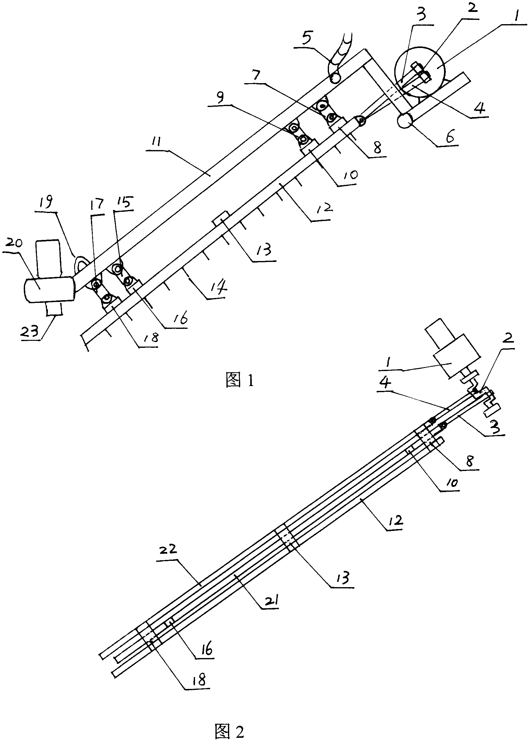
[0012] Accompanying drawing is a kind of concrete embodiment of the present invention, and this embodiment comprises the supporting shaft 6 of slotting machine upper part, the hoisting eye 19 of lower part, and the gravel pump is fixed on the lower end of the slurry steel pipe 11, and the bottom end of the gravel pump is provided with There is a suction port 23, and the upper end of the pulping steel pipe is connected with the pulping rubber hose 5; the upper ends of the rocker arm A7, the rocker arm B9, the rocker arm C15, and the rocker arm D17 are all connected to the pulping steel pipe 11, and the lower end of the rocker arm A7 is connected to the connection A8, and the rocker arm The lower end of B9 is connected to the base 10, the lower end of the rocker arm C15 is connected to the base B16, the lower end of the rocker arm D17 is connected to the connection C18, the connection A8, the connection B13, and the connection C18 are respectively used to connect the upper, middle...


PUM


Abstract

A grooving machine with three saw rods capable of advancing in clay comprises a supporting shaft and a hoisting lug. The supporting shaft is arranged on the upper portion of the grooving machine, the hoisting lug is disposed on the lower portion of the grooving machine, a sandstone pump is fixed at the lower end of a slurry outlet steel tube, a suction opening is arranged at the bottom end of the sandstone pump, and the upper end of the slurry outlet steel tube is connected with a slurry outlet rubber tube; upper ends of a rocker arm A, a rocker arm B, a rocker arm C and a rocker arm D are connected to the slurry outlet steel tube, the lower end of the rocker arm A is connected to a connector A, the lower end of the rocker arm B is connected to a base, the lower end of the rocker arm C is connected to a base B, the lower end of the rocker arm D is connected to a connector C, the connector A, a connector B and the connector C are respectively used for being connected with upper portions, middles and lower portions of a cutter arbor A and a cutter arbor C, and the base A and the base B are respectively disposed at the upper end and the lower end of a cutter arbor B; the left lower end of a connecting rod A is connected to the right upper end of the cutter arbor C via a pin, the right upper end of the connecting rod A is hinged to a crankshaft, the left lower end of a connecting rod B is connected to the right upper end of the cutter arbor B via a pin, the right upper end of the connecting rod B is hinged to the crankshaft, and the left upper end of the crankshaft is connected to a driving power speed reducer; and a plurality of cutter plates are disposed at the bottom of each of the cutter arbor A, the cutter arbor B and the cutter arbor C. The grooving machine is a special machine tool for building underground continuous walls.

Description

1. Technical field [0001] The invention relates to a slotting machine, in particular to a three-saw bar slotting machine for slotting underground continuous walls 2. Background technology: [0002] At present, the saw bar slotting machines used in the construction of underground diaphragm walls are all single saw bar slotting machines. When slotting in clay, the sticky mud adheres between the blades and moves with the blades. Therefore, It is difficult or impossible for general slotting machines to slot in clay. 3. Contents of the invention: [0003] The invention makes up for the shortcomings of the single-saw-bar slotting equipment, and provides a three-saw-bar slotting machine capable of slotting in clay. [0004] The present invention is achieved through the following technical solutions: [0005] A three-saw bar slotting machine, including a support shaft at the upper part of the slotting machine, lifting lugs at the lower part, a sand pump fixed at the lower end of...

Claims


Application Information

Patent Timeline
Patent Type & Authority Patents(China)
IPC IPC(8): E02F5/02E02F7/02E02D5/02
Inventor 陶秀玉向东孙蔚李晶杨霞楚冬梅从容柯婷婷李勇
Owner WATER RESOURCES RES INST OF SHANDONG PROVINCE
Why Eureka
Try Eureka