Ultrasound sensor with a dampening device and use of same

An ultrasonic sensor and attenuation device technology, applied in the field of ultrasonic sensors, can solve problems such as the application of acoustic sensors not proposed

Active Publication Date: 2012-07-11
ROBERT BOSCH GMBH
View PDF8 Cites 0 Cited by
  • Summary
  • Abstract
  • Description
  • Claims
  • Application Information

AI Technical Summary

Problems solved by technology

but no application in acoustic sensors is proposed

Method used


Image

  • Ultrasound sensor with a dampening device and use of same
  • Ultrasound sensor with a dampening device and use of same

Examples


Embodiment Construction

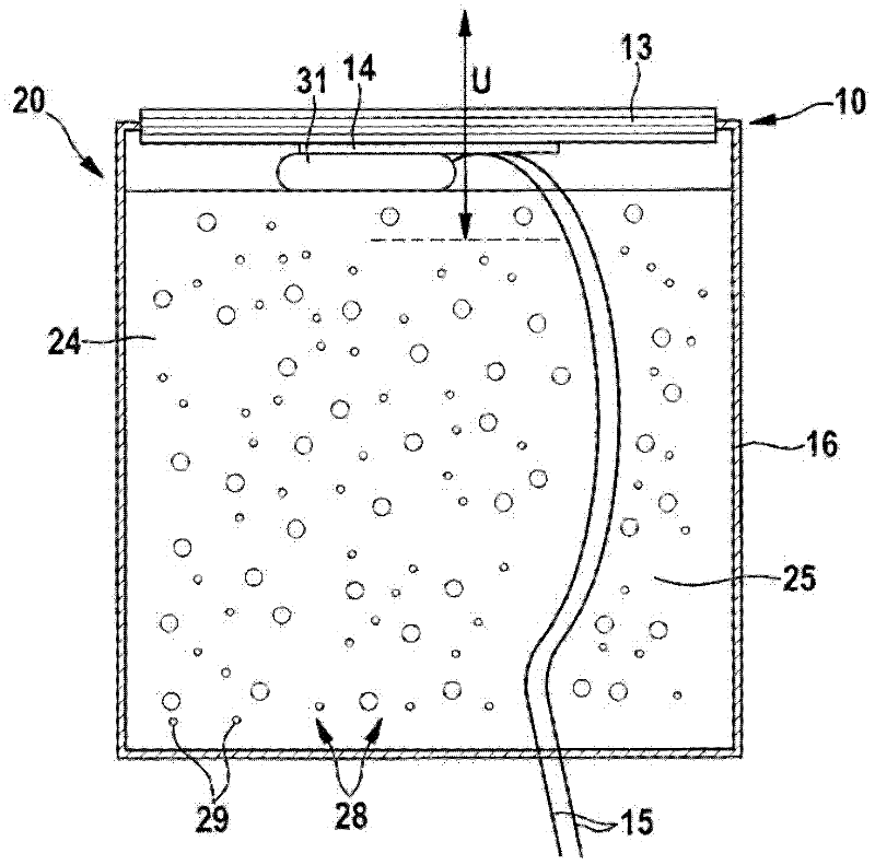
[0022] exist figure 1 In , a preferred embodiment of an ultrasonic sensor 10 is shown in a cross-sectional view. Ultrasonic sensor 10 includes a vibratable membrane 13 for emitting sound waves and preferably also for detecting reflected sound waves. A vibration excitation device 14 is used to excite the diaphragm 13 , which can be realized, for example, in the form of a piezoelectric element. The vibration excitation device 14 is physically connected to the diaphragm 13 here. The electrical lines 15 are used for the energy supply of the vibration excitation device 14 .

[0023] The diaphragm 13 is preferably operated within its resonant frequency range, at figure 1 The vibration mode is clearly shown by the double arrow U in . In this case, the membrane preferably transmits sound waves in the ultrasonic range or detects them.

[0024] In order to realize the fast switching of the ultrasonic sensor 10 from the transmission mode to the reception mode, the vibration of the d...


PUM


Abstract

The invention relates to an ultrasound sensor (10), comprising a vibratory member (13), a vibration stimulator (14), and a damping device (20), wherein the damping device (20) comprises phase change materials.

Description

technical field [0001] The invention relates to an ultrasonic sensor and its use according to the preambles of the independent claims. Background technique [0002] Ultrasonic sensors are used in motor vehicle technology, for example during parking, to monitor the distance of the motor vehicle to obstacles in the vehicle's surroundings and to display the distance to detected obstacles optically or acoustically via a corresponding display device. For this purpose, ultrasonic sensors are arranged, for example, at the front of the vehicle or at the rear of the vehicle on the outer region of the vehicle body. [0003] An ultrasonic sensor suitable for this purpose is known, for example, from DE 103 46 620 A1. The ultrasonic sensor includes a vibrating diaphragm and a piezoelectric element in contact with the diaphragm, and the piezoelectric element excites the diaphragm to vibrate in an ultrasonic range. In order to minimize the energy required to excite the membrane via the p...

Claims


Application Information

Patent Timeline
Patent Type & Authority Applications(China)
IPC IPC(8): G01S15/93G01S7/52G01S7/521
CPCG10K11/002G10K9/122B60R1/00G01S7/521G10K11/00
Inventor A·克洛茨
Owner ROBERT BOSCH GMBH
Why Eureka
Try Eureka