Supercharge Your Innovation With Domain-Expert AI Agents!

Cyclone for separating sticky particles from gas streams

A cyclone separator and particle technology, which can be applied to devices whose axial directions of the cyclone can be reversed, cyclone devices, etc., can solve the problems such as the decrease of the separation efficiency of the cyclone separator.

Inactive Publication Date: 2012-07-11
OUTOTEC OYJ
View PDF8 Cites 3 Cited by
  • Summary
  • Abstract
  • Description
  • Claims
  • Application Information

AI Technical Summary

Problems solved by technology

However, when the gas to be cleaned contains sticky particles, it is disadvantageous when particle accretions occur inside the cyclone, which leads to a decrease in the separation efficiency of the cyclone

Method used


Image

  • Cyclone for separating sticky particles from gas streams
  • Cyclone for separating sticky particles from gas streams
  • Cyclone for separating sticky particles from gas streams

Examples


Embodiment Construction

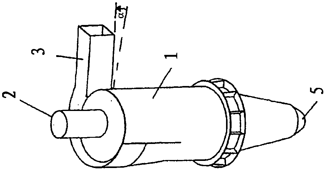
[0016] exist figure 1 , a cyclone separator used to separate sticky particles from a gas stream is shown in three dimensions. It comprises a cylindrical outer wall 1 , an inlet conduit 3 and an outlet 5 for particles. In addition, a dip tube 2 is provided, which is arranged eccentrically in the direction of the inlet conduit 3 . The inlet duct 3 is arranged with an inclination towards the particle outlet 5 in the flow direction, wherein the inclination α lies in the range between 10° and 45°.

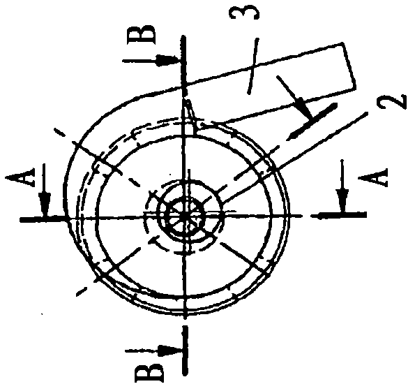
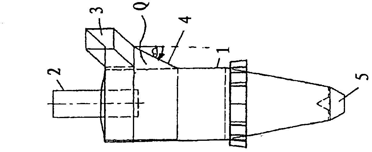
[0017] exist figure 2 , shows a top view of a cyclone separator used to separate sticky particles from a gas stream. The dip tube 2 is arranged eccentrically in the direction of the inlet conduit 3 . exist image 3 In , a cyclone separator for separating sticky particles from the gas flow is shown in view of the inlet duct 3 . At the end of the inlet duct 3 , in the direction of the particle outlet 5 , the flow cross-section has a triangular widening Q, which is formed transvers...


PUM


Abstract

At its end in direction of the particle outlet (5), the flow cross-section of the inlet duct (3) has a triangular expansion Q which laterally is formed by the cylindrical outer wall (1) and by an outer boundary (4). The outer angle of inclination [beta] between the outer boundary (4) and the vertical, proceeding from the end of the inlet duct (3), extends from 30 DEG to 0 DEG in flow direction of the gas streams. Subject-matter of the invention furthermore is the use of the cyclone for separating partly molten particles.

Description

technical field [0001] The present invention relates to a cyclone for separating sticky particles from a gas flow and to the use of the cyclone. Background technique [0002] Centrifugal separators in the form of cyclones are known. In gas purification, for example, they are used to separate solid particles contained in gases. The gases are put into a rotational movement due to their own flow velocity and the corresponding structural design of the cyclone separator. Centrifugal forces acting on the particles accelerate the particles radially outward. In this way they are separated from the air flow which is passed into the interior and discharged. However, when the gas to be purified contains sticky particles, it is disadvantageous if particle accretions occur inside the cyclone separator, which leads to a reduction in the separation efficiency of the cyclone separator. Great efforts have to be made to interrupt the gas cleaning in the cyclone separator and the cyclone s...

Claims


Application Information

Patent Timeline
IPC IPC(8): B04C5/04B04C5/13
CPCB04C5/13B04C5/04B29B9/16
Inventor M·米萨拉M·施米茨
Owner OUTOTEC OYJ
Features
  • R&D
  • Intellectual Property
  • Life Sciences
  • Materials
  • Tech Scout
  • Unparalleled Data Quality
  • Higher Quality Content
  • 60% Fewer Hallucinations
Learn More