Handle device

A technology for handles and equipment, which is applied to wing handles, mechanical equipment, devices to prevent keys from being removed from locks, etc. It can solve the problems of complex assembly of locking units, increased weight, and the inability to completely eliminate the opening of vehicle doors.

Inactive Publication Date: 2012-07-11
HUF HULSBECK & FURST GMBH & CO KG
View PDF7 Cites 16 Cited by
  • Summary
  • Abstract
  • Description
  • Claims
  • Application Information

AI Technical Summary

Problems solved by technology

It proved to be a disadvantage that the assembly of a reliably working locking unit with mass elements is complicated
At the same time, the weight of the entire facility increases due to the use of mass elements
It has also been shown that the mere provision of mass elements in the locking unit does not completely preclude opening of the vehicle door in extreme cases in the event of a side impact

Method used


Image

  • Handle device
  • Handle device
  • Handle device

Examples


Embodiment Construction

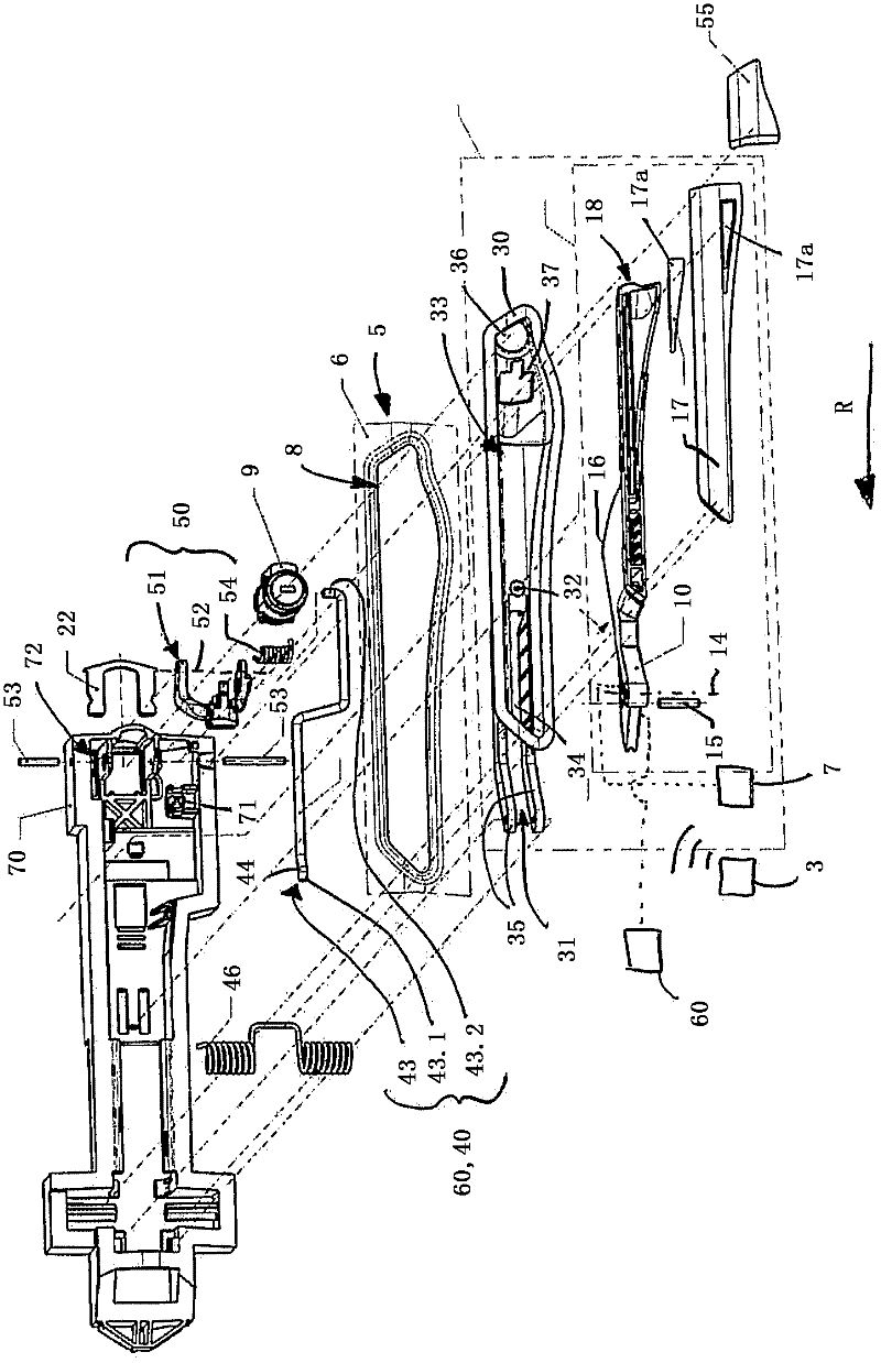
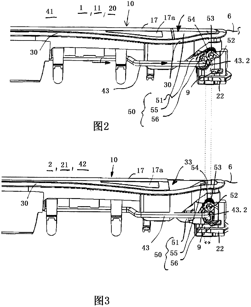
[0036] figure 1 A possible embodiment variant of a handle arrangement for a locking device 7 of a vehicle is shown. Locking device 7 in figure 1 It is shown purely schematically. The locking device 7 is a component of a keyless-operating security system of the vehicle, in particular of an access and / or travel authorization control system. The security system can, for example, be in data communication with the ID transmitter 3 , whereby an authentication between the ID transmitter 3 and the security system can be carried out when the user, in particular, operates on the ID transmitter 3 or on the handle device intentionally. When positively identified, the locking device 7 can be brought from the locked state 20 into the unlocked state 21 (see also figure 2 , 3 , 6a and 6b). In the unlocked state 21 , for example, the doors of the vehicle can be opened, which will be discussed further below.

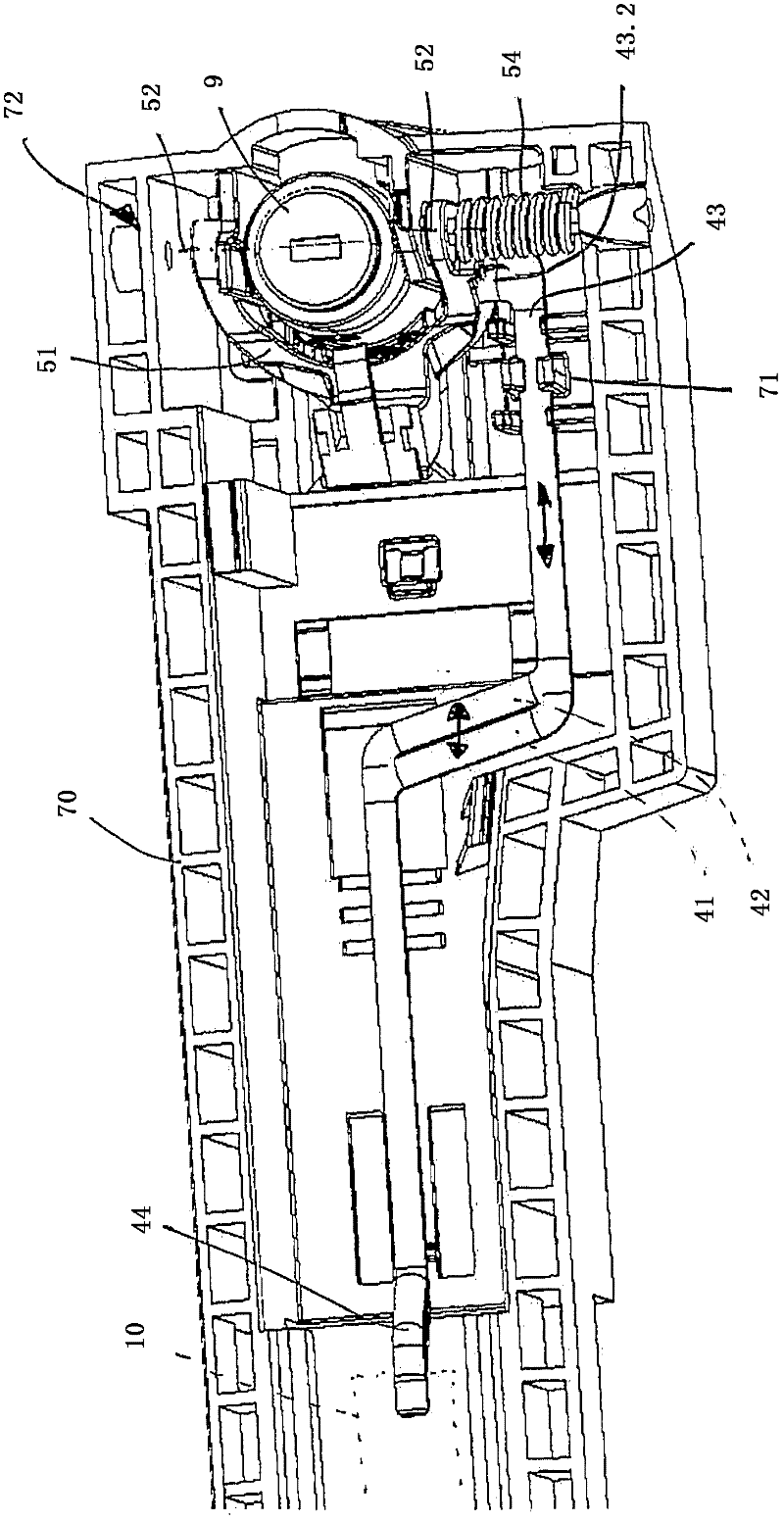
[0037] The handle device has a handle part 10 mounted so as to be movable rela...


PUM


Abstract

The invention relates to a handle device for a lock unit (7) of a vehicle, comprising a handle part (10) which is movably mounted relative to a door (5) of the vehicle, a locking unit (40) for preventing unintentional opening of the door (5) caused by accelerations acting upon the handle part (10), especially accelerations such as they act upon the vehicle during a crash, the locking unit (40) being displaceable between a locking position (1) and a release position (2), and a movement of the handle part (10) being enabled in the release position (2) and a movement of the handle part (10) being disabled in the locking position (1). The invention is characterized in that an actuating unit (50) is actively connected to the locking unit (40) such that the locking unit (40) can be brought from the locking position (1) into the release position (2) when the actuating unit (50) is activated.

Description

technical field [0001] The invention relates to a handle device for a locking device of a vehicle, with a handle part which is supported in a movable manner relative to a door of the vehicle, and with means for preventing the door from acting on the handle part, especially in the event of an accident A locking unit that undesirably opens under the influence of accelerations acting on the vehicle, wherein the locking unit is displaceable between a locked position and a released position, wherein in the released position the handle part is enabled to move and in the locked position to prevent movement of the handle parts. Furthermore, the invention relates to a method for operating a handle device. Background technique [0002] It is known to use locking units as crash locks in handle devices. It is known, for example, from DE 199 49 119 A1 to use the mass element of a locking unit due to its inertia for securing a vehicle door in the event of an accident. In this case, the...

Claims


Application Information

Patent Timeline
Patent Type & Authority Applications(China)
IPC IPC(8): E05B5/02E05B13/00E05B65/12E05B77/54
CPCE05B85/103E05B85/107E05B77/04E05B17/10E05B81/76Y10T292/57
Inventor 迪尔克·米勒马里奥·克里斯滕森斯特凡·默尼希克里斯托夫·布劳纳马丁·维特诺贝特·黑勒
Owner HUF HULSBECK & FURST GMBH & CO KG
Why Eureka
Try Eureka