Video display device

A technology of video display, video frame, applied in the direction of TV, static indicator, standard conversion, etc.

Inactive Publication Date: 2014-12-24
SHARP KK
View PDF2 Cites 0 Cited by
  • Summary
  • Abstract
  • Description
  • Claims
  • Application Information

AI Technical Summary

Problems solved by technology

The technique disclosed in [0016] Patent Document 1 is a technique for accurately detecting a motion vector of a moving telop portion to prevent video degradation of the moving telop portion. , the technology disclosed in Patent Document 2 is a technology that detects motion vectors in a video such as a plurality of moving objects intersecting with high precision to suppress damage to the entire video. Video degradation occurs at the boundary portion between

Method used


Image

  • Video display device
  • Video display device
  • Video display device

Examples


Embodiment 1

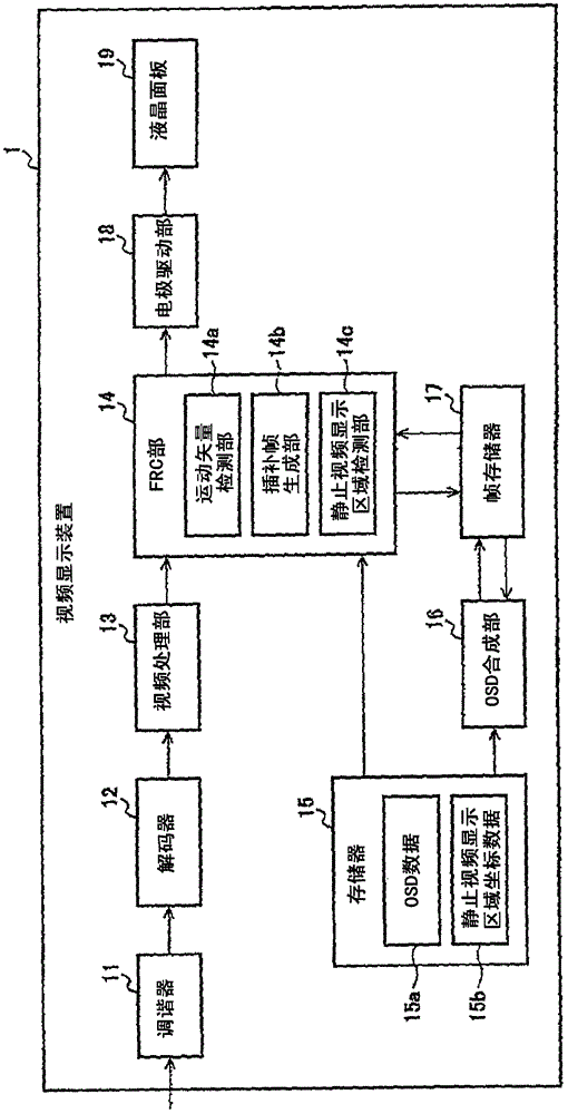
[0030] figure 1 is a functional block diagram of the video display device according to the present invention. Video display device 1 is composed of tuner 11 , decoder 12 , video processing unit 13 , FRC unit 14 , memory 15 , OSD synthesis unit 16 , frame memory 17 , electrode driver unit 18 , and liquid crystal panel 19 .

[0031] The tuner 11 selects a desired channel from digital broadcast signals received by an antenna (not shown), and outputs a digital reception signal of the selected channel to the decoder 12 . The decoder 12 decodes the encoded digital reception signal to generate a video signal, and outputs the generated video signal to the video processing unit 13 . The video processing unit 13 performs image quality correction such as γ correction and color correction on the video signal input from the decoder 12 , and outputs the image quality corrected video signal to the FRC unit 14 .

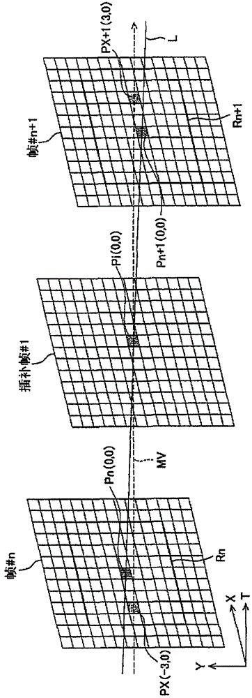
[0032] The FRC unit 14 extracts two consecutive frames (original frames) fro...

Embodiment 2

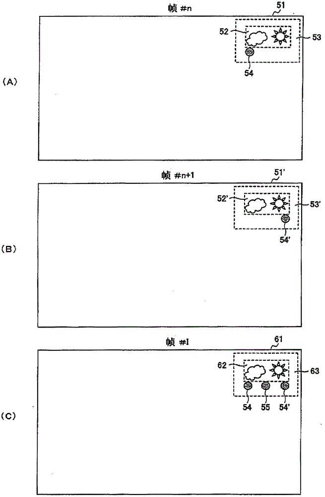
[0067] For example, a telop (still video) may be displayed over the entire horizontal width of the upper part of the screen like a news bulletin or the like. At this time, as described in Embodiment 1, if the predetermined threshold is set to 50% of the number of pixels in the horizontal width of the still video display area, the magnitude of the motion vector of the object will not be considered to exceed the predetermined threshold. Threshold (it will not be considered that the object moves from the left end of the screen to the right end at high speed between two frames). Therefore, in general, in the still video display area 62 and the surrounding area 63 of the interpolation frame #1, the video of the still video display area 52 and the surrounding area 53 of the frame #n may be displayed, resulting in that the video cannot be displayed smoothly.

[0068] Figure 4 Shows a functional block diagram of the video display device of Embodiment 2, where the video display devic...


PUM


Abstract

Disclosed is an image displaying apparatus which executes FRC process, wherein image deterioration in a boundary portion between a still image display area and its periphery is prevented. When the magnitude of the motion vector of an object (54) in the periphery (53) of a still image display area (52) is less than a predetermined threshold value, an interpolation frame generation portion (14b) of the present invention defines the pixel values of a still image display area (52) and its periphery (53) of the frame #n as the interpolation pixel values of a still image display area (62) and its periphery (63)of the interpolation frame #I. Further, when the magnitude of the motion vector of the object (54) is equal to or greater than the predetermined threshold value, the pixel values of the still image display area (52') and its periphery (53') of the frame #n+1 are defined as the interpolated pixel values of the still image display area (62) and its periphery (63) of the interpolation frame #I.

Description

technical field [0001] The present invention relates to a video display device that performs frame rate conversion processing, and more particularly, to a video display device that prevents video degradation from occurring when frame rate conversion processing is performed. Background technique [0002] In a video display device having a liquid crystal panel, in order to suppress the afterimage when displaying moving images and improve the image quality, the frame rate (number of frames) of the video signal per unit time is increased to increase the frame rate of the resolution in the time direction. Conversion (hereinafter referred to as FRC) processing. [0003] The FRC process performs processing of detecting a motion vector of an object from a difference between a plurality of (usually 2) frames contained in a video signal to make an interpolation frame (also referred to as an interpolation frame), and It is inserted between frames. [0004] In video display devices th...

Claims


Application Information

Patent Timeline
Patent Type & Authority Patents(China)
IPC IPC(8): H04N7/01G02F1/133G09G3/20G09G3/36
CPCG09G2360/16G09G3/20G09G2340/16G09G2320/0257H04N7/013G09G2320/106G09G2340/0435
Inventor 渡边美保子
Owner SHARP KK
Why Eureka
Try Eureka