Virtual image display magnifying device and display device

A technology for magnifying devices and virtual images, applied in optical components, instruments, optics, etc., can solve the problems of immature mass production technology and high manufacturing cost, and achieve the effect of improving viewing experience, low cost, and comfortable viewing experience

Pending Publication Date: 2022-02-18
郭吉庆
View PDF0 Cites 1 Cited by
  • Summary
  • Abstract
  • Description
  • Claims
  • Application Information

AI Technical Summary

Problems solved by technology

It is necessary to use micro-displays and optical engines and optical lenses with high technical thresholds to meet performance specifications. The mass production technology is still immature and the manufacturing cost is high.

Method used


Image

  • Virtual image display magnifying device and display device
  • Virtual image display magnifying device and display device
  • Virtual image display magnifying device and display device

Examples


Embodiment 1

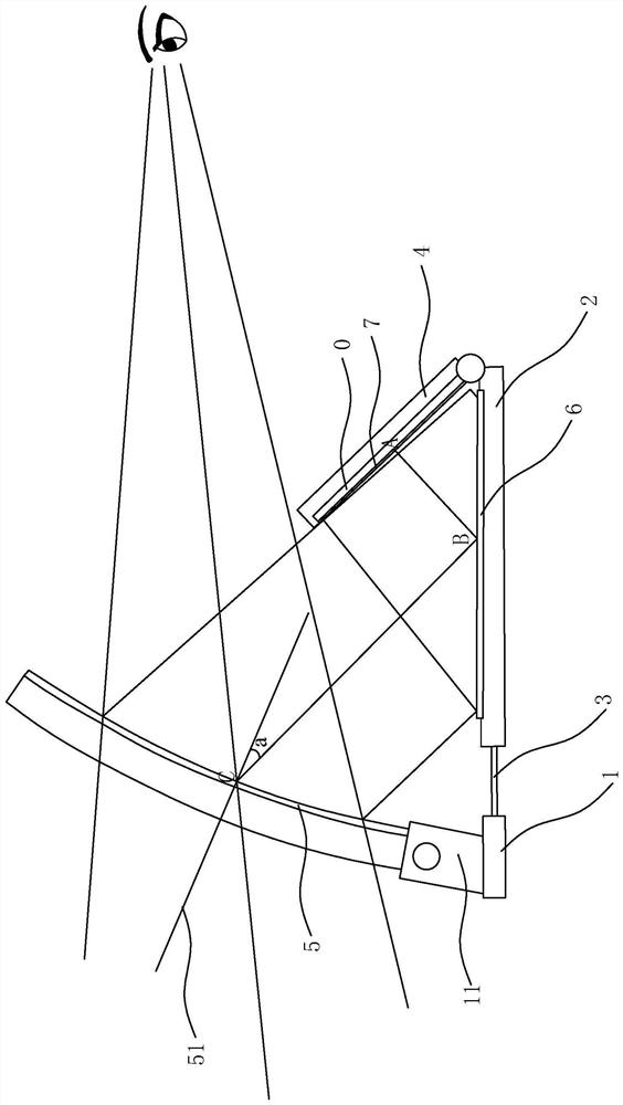
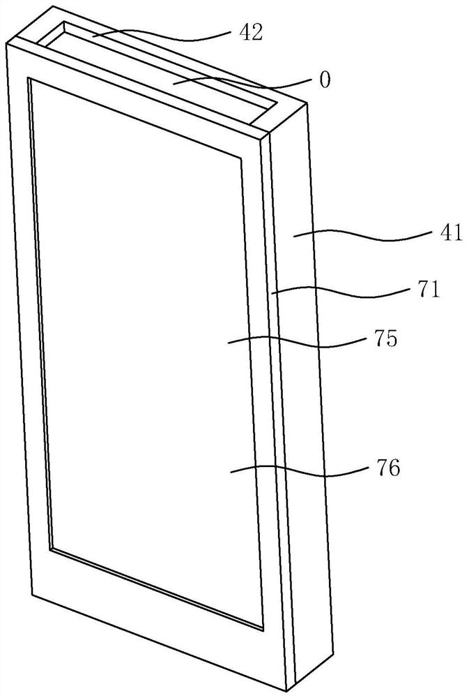
[0038] like Figure 1 to 4 As shown, the virtual image display amplification device is used to enlarge the image of the display device 0, which can be a mobile phone or other device. The amplifying device includes a first bracket 1, a second bracket 2, a connecting mechanism 3, a bracket 4, a first reflective device 5, a second reflecting device 6, and a polarizing apparatus 7, a first bracket 1, a second bracket 2 interval. The arrangement, the connecting mechanism 3 is disposed between the first bracket 1, and the second bracket 2 is adjusted between the two, the bracket 4 can be rotatably disposed at the second bracket 2 end, and the display device is set in the bracket 4. On the upper, the polarized light polarization device 7 is close to the display device screen setting, and there is no gap between the polarization polarization device 7 and the display device screen, thereby avoiding scattering between the display device screen and the polarization light polarizer 7. And the ...

Embodiment 2

[0044] The difference between the embodiment and the implementation is:

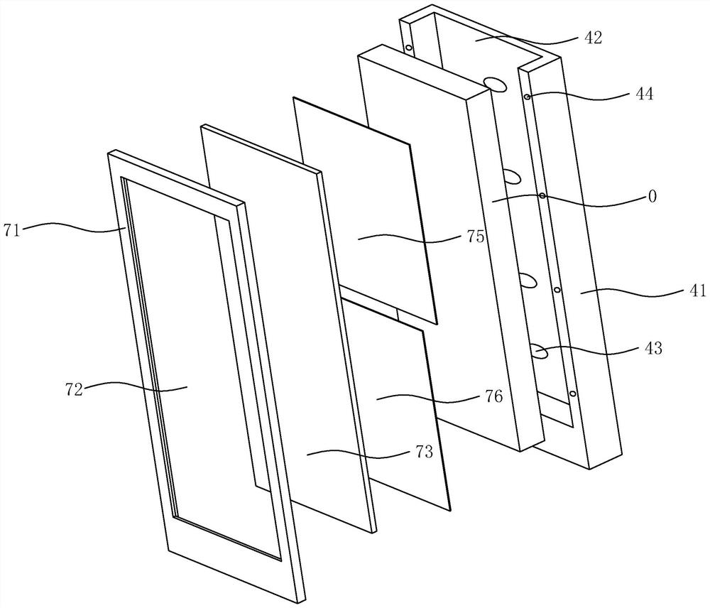
[0045] In the first embodiment, the P-light polarization polarizing plate 75 and the S-light polarizing polarizing plate 76 are arranged by mounting frame, in this embodiment, such as Image 6 As shown, the P-photographic polarization polarizing plate 75 and the S-light polarization polarizing plate 76 are disposed on the display device screen, that is, as integral with the display device screen, the P-light polarization polarizing plate 75 and the S-light polarization polarizing plate 76 The optical axis symmetry of the display device. Among them, the light pallographic polarization piece can be Wave plate or Waves can select the appropriate P-light polarization polarizing plate 75 and the S-light polarization polarizing plate 76 according to the specific parameters of the display device screen.

Embodiment 3

[0047] like Figure 7 As shown, the virtual image display amplifying device is used to enlarge the image of the display device 0, including the first bracket 1, the second bracket 2, the connecting mechanism 3, the bracket 4, the first reflecting device 5, and the polarization light polarizer 7, A bracket 1, the second bracket 2 is arranged, and in the same plane, the connecting mechanism 3 is disposed between the first bracket 1, and the second bracket 2 is adjusted between the intervals between the two, the bracket 4 rotatably placed in the first The two bracket 2 ends, the display device 0 is disposed on the bracket 4, and the polarized light polarization device 7 is stuck in the display device screen setting, and there is no gap between the polarized light polarization device 7 and the display device screen, thereby avoiding light in display. A scattering between the device screen and the polarization light polarizer 7, and causes the amplified image to have a dark band, the fi...


PUM


Abstract

The invention provides a virtual image display magnifying device and a display device, the virtual image display magnifying device comprises a first support, a second support, a connecting mechanism, a bracket, a first reflecting device, a second reflecting device and a polarized light polarization device, the connecting mechanism is arranged between the first support and the second support to adjust the interval between the first support and the second support, and the bracket is rotatably arranged at the end part of the second support. The polarized light polarization device is tightly attached to the screen of the display equipment, the first reflecting device is rotatably arranged at the end of the first support, the second reflecting device is arranged at the upper end of the second support, and the first reflecting device comprises a curved mirror surface. During use, the display equipment tilts for 30-60 degrees relative to the second reflecting device, the first reflecting device receives light from the second reflecting device, and the angle of the incidence angle of the light relative to the center line of the main shaft of the curved mirror surface is 5-45 degrees. According to the invention, the magnified image content can be watched in an open environment, the eyes are not pressed, the high-quality resolution, contrast ratio and brightness are achieved, and the use is flexible and convenient.

Description

Technical field [0001] The present invention relates to a virtual image display amplifying device and a display device. Background technique [0002] Existing 3D virtual palm devices are usually three technologies: mobile phone embedded technology, dual screen display technology and Ar, MR display technology. Mobile phone embedded technology is to place the phone in front of the eye, and placed in the eye mask, the magnifying lens is close to the eyes and mobile screens, and the 3D piece source content of the mobile phone is still required to meet the viewing perspective, due to viewing perspective The eye is very close to the screen of the mobile phone, and the eyes are oppressed, affecting the viewing experience. Double-screen display technology requires two display, and the two displays are arranged for left and right eye. The angled eye mask is also placed, the magnifying lens is close to the display, which is displayed in a closed environment, mainly applied to 3D game conte...

Claims


Application Information

Patent Timeline
Patent Type & Authority Applications(China)
IPC IPC(8): G02B27/01G02B30/25
CPCG02B27/0172G02B27/0176G02B30/25
Inventor 郭吉庆
Owner 郭吉庆
Why Eureka
Try Eureka