Safety valve of electric water heater

A technology for electric water heaters and safety valves, applied in the field of safety valves, can solve the problems of shortened service life of safety valves, high production costs, and low production efficiency, and achieve the effects of reasonable structure setting, low production costs, and simple structure

Inactive Publication Date: 2013-01-16
ZHEJIANG HUAYI PRECISION MACHINERY CO LTD
View PDF5 Cites 12 Cited by
  • Summary
  • Abstract
  • Description
  • Claims
  • Application Information

AI Technical Summary

Problems solved by technology

[0002] The structure of the safety valve of the existing electric water heater is unreasonable. When the safety valve is opened to release the pressure or discharge the sewage at the bottom of the water heater, the parts in the pressure relief valve will directly contact the water heater or sewage, which often easily makes the spring in it rust, causing The service life of the safety valve is shortened or the pressure limit fails. In addition, the resistance of the seal at the tie rod of the safety valve is relatively large, and it cannot be automatically reset after leakage, which affects the function of the safety valve. The structure of the safety valve is complicated, the production efficiency is low, and the production cost is high.

Method used


Image

  • Safety valve of electric water heater
  • Safety valve of electric water heater
  • Safety valve of electric water heater

Examples


Embodiment Construction

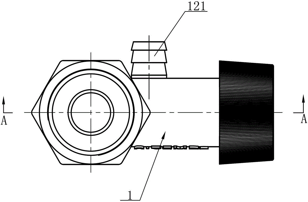
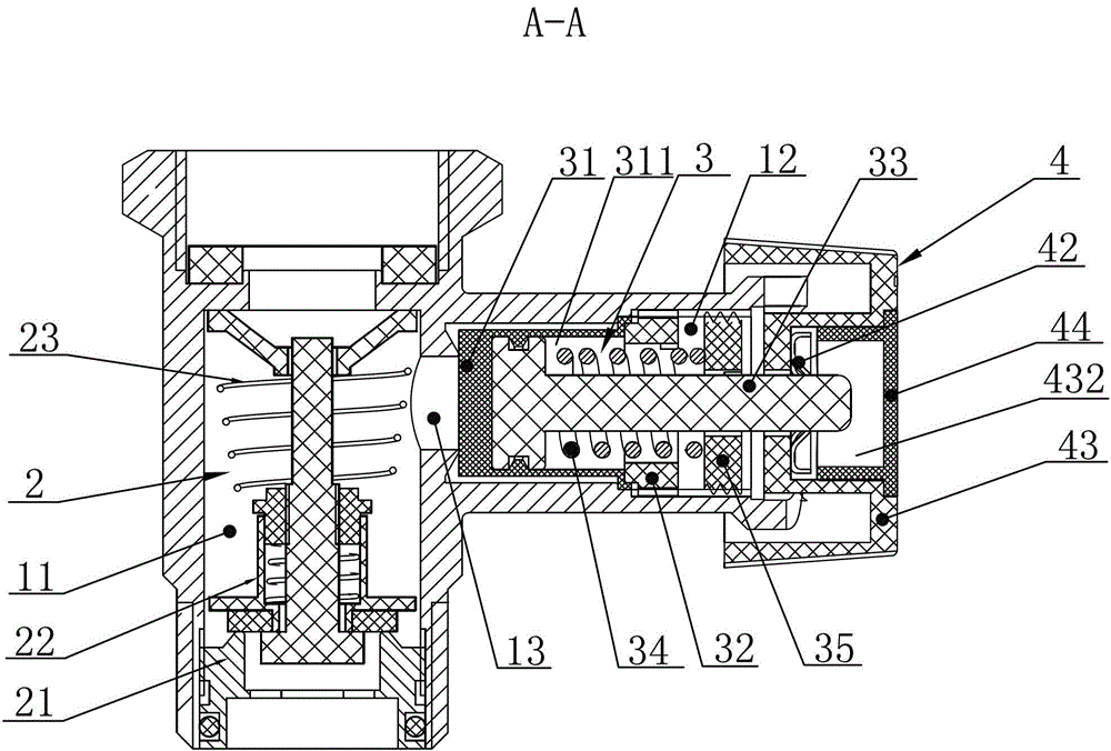
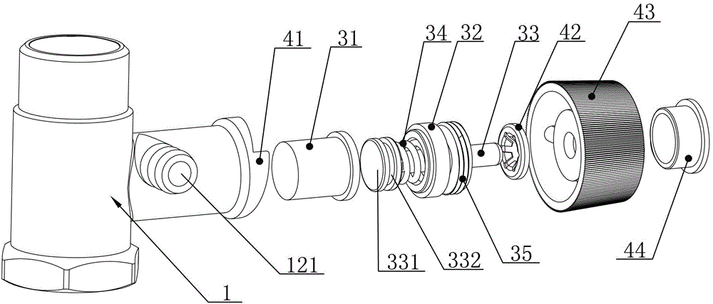
[0023] see Figure 1 to Figure 8 , a safety valve for an electric water heater disclosed in the present invention includes a valve body 1, a water inlet chamber 11 and a pressure relief chamber 12 are arranged on the valve body 1, and a water inlet chamber 11 and a pressure relief chamber 12 are arranged between A water inlet channel 13, the water inlet chamber 11 is provided with a one-way water inlet valve 2, the pressure relief chamber 12 is provided with a drain nozzle 121, and the pressure relief chamber 12 is provided with a pressure relief valve 3, the pressure relief valve 3 Including a rubber body 31, a rubber body pressure cap 32, a pull rod 33, a return spring 34 and an adjustment cap 35, the rubber body 31 is provided with a cavity 311, and the rubber body pressure cap 32 is threadedly connected to the inner wall of the pressure relief chamber 12 , the inner end of the pull rod 33 is inserted into the cavity 311 through the rubber body pressure cap 32 and fixedly c...


PUM


Abstract

The invention discloses a safety valve of an electric water heater. The safety valve comprises a valve body, and a water inlet cavity and a pressure relief cavity, which are arranged on the valve body; a one-way water inlet valve is arranged in the water inlet cavity; a pressure relief valve is arranged in the pressure relief cavity; the pressure relief valve comprises a rubber body, a rubber body pressing cap, a pull rod, a return spring and an adjustment cap; an empty cavity is arranged in the rubber body; the rubber body pressing cap is in threaded connection with the inner wall of the pressure relief cavity; an inner end of the pull rod passes through the rubber body pressing cap, is inserted into the empty cavity, and is fixedly connected with the inner wall of the empty cavity; the rubber body is arranged into a columnar barrel-shaped structure; the edge of the rubber body outwards extends to the rubber body pressing cap to be hermetically fixed; the adjustment cap is arranged at the outer end of the rubber body pressing cap; the return spring is sleeved on the pull rod; an inner end of the return spring is connected with the inner end of the pull rod; an outer end of the return spring is butted against the adjustment cap; and the rubber body is hermetically jacked on an outlet of a water inlet passage under the action of the return spring. The safety valve is reasonable in structural arrangement, and compact and simple in structure, and is reliable to work; the production cost is low; and furthermore, the service life is long.

Description

technical field [0001] The invention relates to the technical field of safety valves, in particular to an electric water heater safety valve. Background technique [0002] The structure of the safety valve of the existing electric water heater is unreasonable. When the safety valve is opened to release the pressure or discharge the sewage at the bottom of the water heater, the parts in the pressure relief valve will directly contact the water heater or sewage, which often easily makes the spring in it rust, causing The service life of the safety valve is shortened or the pressure limit fails. In addition, the resistance of the seal at the tie rod of the safety valve is relatively large, and it cannot be automatically reset after leakage, which affects the function of the safety valve. The structure of the safety valve is complicated, the production efficiency is low, and the production cost is high. . Contents of the invention [0003] In view of the deficiencies in the p...

Claims


Application Information

Patent Timeline
Patent Type & Authority Applications(China)
IPC IPC(8): F16K17/06F16K17/164F16K15/06
Inventor 曾奇有罗占涛姚海峰
Owner ZHEJIANG HUAYI PRECISION MACHINERY CO LTD
Why Eureka
Try Eureka