Check patentability & draft patents in minutes with Patsnap Eureka AI!

Refrigeration system and its thermal expansion valve

A thermal expansion valve and spool technology, applied in thermal expansion valves and refrigeration systems, can solve the problems that the system pressure difference cannot be completely zero, no balance is achieved, and the 3′1 adjustment accuracy of the valve core is affected, so as to reduce the system pressure. The effect of reducing the system pressure difference and improving the adjustment accuracy

Active Publication Date: 2015-08-26
ZHEJIANG SANHUA COMMERCIAL REFRIGERATION CONTROLS CO LTD SHAOXING CITY
View PDF9 Cites 0 Cited by
  • Summary
  • Abstract
  • Description
  • Claims
  • Application Information

AI Technical Summary

Problems solved by technology

[0009] Although, figure 1 The thermostatic expansion valve shown can achieve two-way balanced flow, but this balance is only a basic balance, and the system pressure difference is not completely zero, and complete balance has not been achieved
Specifically, such as figure 1 As shown, since the connection between the transmission plate 3'3 and the transmission rod 3'2 is a gap connection, the pressure of the refrigerant in the lower chamber 2'3 acts on the upper end surface of the transmission rod 3'2, and then feeds the valve There is a downward force on the spool 3'1. The existence of this force makes the system pressure difference not completely zero, so it will still affect the adjustment accuracy of the spool 3'1.
[0010] It should be noted that, when the transmission plate 3′ 3 and the transmission rod 3′ 2 are in a sealed connection and there is no gap between the two, the transmission plate 3 ′ 3, the transmission rod 3 ′ 2 and the valve The core 3′1 is taken as the force analysis object as a whole. At this time, the top surface of the transmission piece 3′3 will still receive a downward force generated by the pressure of the refrigerant in the lower chamber 2′3. The force-bearing area of ​​the force is That is, the sealing area between the transmission rod 3'2 and the transmission plate 3'3, that is, the area of ​​the upper end surface of the transmission rod 3'2, and then the valve core 3'1 will still be subjected to a downward force. The existence of force makes the pressure difference of the system not completely zero, which will still affect the adjustment accuracy of the spool 3′1

Method used


Image

  • Refrigeration system and its thermal expansion valve
  • Refrigeration system and its thermal expansion valve
  • Refrigeration system and its thermal expansion valve

Examples


Embodiment Construction

[0041] The core of the present invention is to provide a thermal expansion valve. The structural design of the thermal expansion valve can reduce the system pressure difference on the valve core components, thereby improving the adjustment accuracy of the valve core components. In addition, another core of the present invention is to provide a refrigeration system including the thermal expansion valve.

[0042] In order to enable those skilled in the art to better understand the technical solutions of the present invention, the present invention will be further described in detail below in conjunction with the accompanying drawings and specific embodiments.

[0043] First of all, it should be noted that the "up, down, left, and right" mentioned in this article are all references to the positions shown in the drawings, and thus cannot be used as limitations on the protection scope of the present invention.

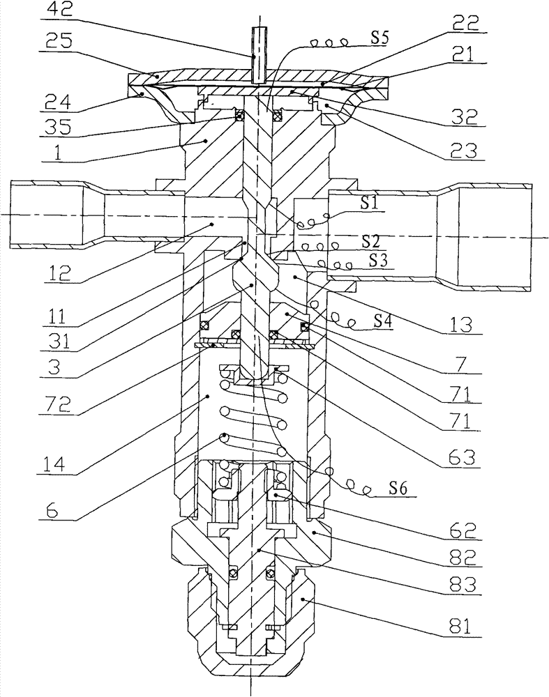
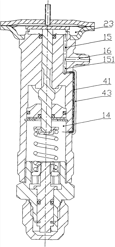
[0044] Please refer to figure 2 , image 3 , Figure 13-1 , Figu...


PUM


Abstract

The invention discloses a thermostatic expansion valve, which comprises a valve body provided with an air tank at the upper end and having an inner cavity divided into an upper cavity and a lower cavity by a diaphragm; a valve core part and a valve port matched with each other and arranged in the inner cavity of the valve body; and a balancing chamber balancing the valve core part and arranged at the lower end part of the valve body. The thermostatic expansion valve is characterized in that a sealing part is arranged between the balancing chamber and the inner cavity of the valve body, and isolates and seals the balancing chamber and the inner cavity of the valve body; and the balancing chamber is communicated with the lower cavity. The structure design of the thermostatic expansion valve can reduce system pressure difference of the valve core part, to thereby improve the regulation accuracy of the valve core part. In addition, the invention also discloses a heat exchange device comprising the thermostatic expansion valve.

Description

technical field [0001] The invention relates to the technical field of refrigerant fluid control components, in particular to a thermal expansion valve. In addition, the present invention also relates to a refrigeration system comprising the thermal expansion valve. Background technique [0002] The thermal expansion valve is an important part of the refrigeration system, and it is another basic part of the four basic components of the refrigeration system except the evaporator, compressor and condenser. The main function of the thermal expansion valve is to control the opening of the valve by sensing the superheat of the outlet end of the evaporator or the suction end of the compressor in the refrigeration system, so as to achieve the purpose of regulating the flow of refrigerant in the system and throttling and reducing pressure. [0003] Please refer to figure 1 , figure 1 It is a structural schematic diagram of a typical thermal expansion valve in the prior art. [0...

Claims


Application Information

Patent Timeline
Patent Type & Authority Patents(China)
IPC IPC(8): F25B41/06
Inventor 刘长青
Owner ZHEJIANG SANHUA COMMERCIAL REFRIGERATION CONTROLS CO LTD SHAOXING CITY
Features
  • R&D
  • Intellectual Property
  • Life Sciences
  • Materials
  • Tech Scout
  • Unparalleled Data Quality
  • Higher Quality Content
  • 60% Fewer Hallucinations
Learn More