High-precision pose adjusting device for spliced grating

A pose adjustment, high-precision technology, applied in the direction of installation, optics, optical components, etc., can solve problems such as the inability to realize multi-degree-of-freedom grating precision adjustment, and achieve motion coupling problems, high adjustment accuracy, and high-precision pose adjustment Effect

Inactive Publication Date: 2011-08-17
HARBIN INST OF TECH
View PDF4 Cites 32 Cited by
  • Summary
  • Abstract
  • Description
  • Claims
  • Application Information

AI Technical Summary

Problems solved by technology

[0004] The purpose of the present invention is to solve the problem that the existing high-precision grating attitude adjustment device cannot realize the precise adjustment of multi-degree-of-freedom gratings, and to provide a high-precision attitude adjustment device for splicing gratings

Method used


Image

  • High-precision pose adjusting device for spliced grating
  • High-precision pose adjusting device for spliced grating
  • High-precision pose adjusting device for spliced grating

Examples


specific Embodiment approach 1

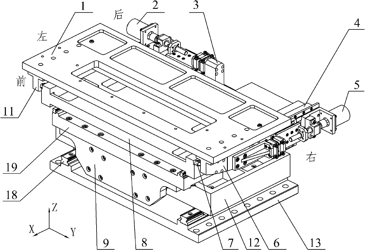
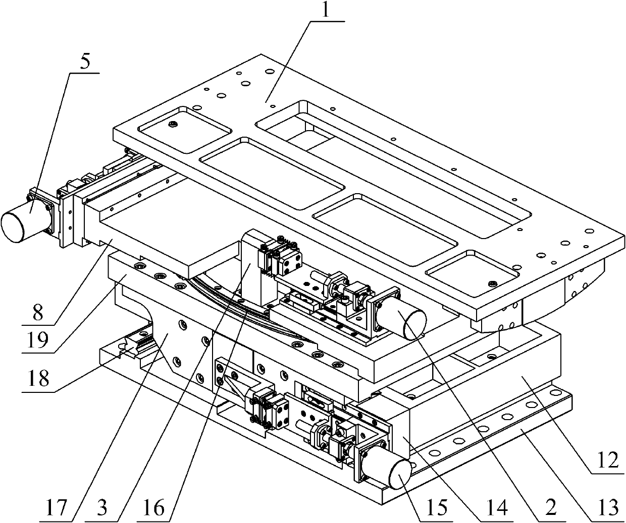
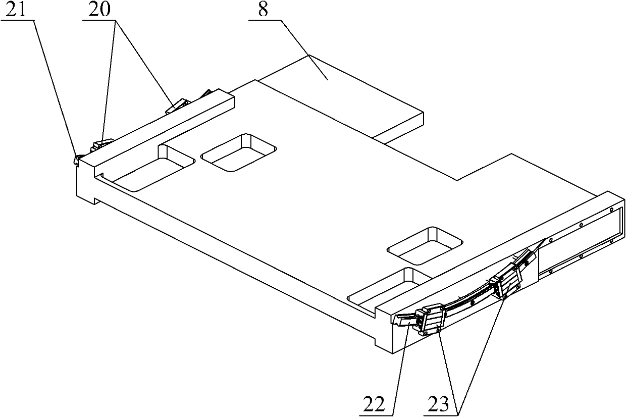
[0016] Specific implementation mode one: combine Figure 1 to Figure 6 Describe this embodiment. The high-precision pose adjustment device in this embodiment is composed of a pitch adjustment unit, a yaw adjustment unit, an in-plane adjustment unit, a straight line adjustment unit, and an adjustment base 13; the pitch adjustment unit is composed of a pitch adjustment plate 1, The pitch adjustment right guard plate 6, the pitch adjustment left guard plate 11, the pitch adjustment guide rail assembly 7, the pitch adjustment micro-driver 5 and the pitch adjustment connector 4 are composed, and the pitch adjustment guide rail assembly 7 is composed of a pitch adjustment left circular arc Guide rail 21, a section of pitch adjustment right circular arc guide rail 21, a pair of pitch adjustment left guide rail sliders 20 and a pair of pitch adjustment right guide rail sliders 23;

[0017] The yaw adjustment unit is composed of a yaw adjustment frame 8, a yaw adjustment micro-driver 2...

specific Embodiment approach 2

[0028] Specific implementation mode two: combination figure 1 , figure 2 , Figure 7 with Figure 8 Description, the pitch adjustment micro-driver 5 of the present embodiment is made up of pitch stepper motor 33, pitch motor base 34, pitch motor coupling 35, pitch bearing block 36, pitch ball screw 37, pitch screw nut 38, pitch reference plane Support plate 39, pitch micro-drive guide rail slider 49, pitch micro-drive linear guide 52, pitch adjustment locking backing plate 50, pitch adjustment locking plate 48, pitch column plane plate 40, pitch steel ball 41, pitch spring 47, pitch Steel ball seat 42, pitching steel ball supporting plate 46, pitching push plate 43, pitching adjustment connecting bent plate 44, pitching micro-drive base 51, four pitching first hanging spring screws 45 and four pitching second hanging spring screws 69 composition;

[0029] The output end of the pitching stepper motor 33 is connected to one end of the pitching ball screw 37 through the pitc...

specific Embodiment approach 3

[0030] Specific implementation mode three: combination figure 1 , figure 2 , Figure 9 with Figure 10 Explain that the yaw adjustment micro-driver 2 of the present embodiment is composed of a yaw stepper motor 70, a yaw motor base 71, a yaw motor coupling 72, a yaw bearing seat 73, a yaw ball screw 74, and a yaw wire. Bar nut 75, yaw reference plane support plate 76, yaw micro-drive guide rail slider 77, yaw micro-drive linear guide 78, yaw adjustment locking backing plate 79, yaw adjustment locking plate 80, yaw column flat Panel 81, yaw steel ball 82, yaw spring 83, yaw steel ball seat 84, yaw steel ball supporting plate 85, yaw push plate 86, yaw adjustment connecting bent plate 87, yaw micro-drive base 88 , four yaw first hanging spring screws 89 and four yaw second hanging spring screws 90;

[0031]The output end of the yaw stepping motor 70 is connected to one end of the yaw ball screw 74 through the yaw motor coupling 72. The yaw ball screw 74 is supported by the ...


PUM


Abstract

The invention discloses a high-precision pose adjusting device for a spliced grating, and relates to a high-precision pose adjusting device for a grating set. The device solves the problem that the high-precision grating pose adjusting device cannot realize precise grating adjustment of multiple degrees of freedom. A pitch adjusting unit is driven by a pitch adjusting micro driver to drive a pitch adjusting right guide rail sliding block to slide on a corresponding guide rail so as to realize directional independent grating adjustment; a deflection adjusting unit is driven by a deflection adjusting micro driver to drive a deflection adjusting framework and front and rear deflection guide rail sliding blocks to slide on the corresponding guide rails so as to realize directional independent grating adjustment; an in-plane adjusting unit is driven by an in-plane adjusting micro driver to drive an in-plane adjusting front and rear guide rail sliding blocks to slide on the corresponding guide rails so as to realize independent grating adjustment; and a linear adjusting unit is driven by a linear adjusting micro driver to drive a linear adjusting framework and left and right linear guide rail sliding blocks to slide on the corresponding guide rails so as to realize directional independent grating adjustment. The device is used for high-precision pose adjustment of the spliced grating set.

Description

technical field [0001] The invention relates to a high-precision pose adjustment device for a grating group. Background technique [0002] Large-aperture diffraction gratings play an important role in many technical fields, such as spectroscopic astronomical telescope systems, inertial confinement fusion systems, and synchrotron radiation systems. At present, it is technically and economically impractical to directly manufacture large-aperture high-quality multilayer dielectric film gratings. Therefore, it is important to realize large-aperture high-quality diffraction gratings by splicing several small gratings into a large-aperture grating. means. Generally speaking, a grating compressor needs to be built for the spliced ​​grating group. The grating groups in the compressor need to adjust their relative positions to compress the pulse. The grating position and attitude adjustment device is a key device to realize the precise adjustment of the mutual position relationshi...

Claims


Application Information

Patent Timeline
Patent Type & Authority Applications(China)
IPC IPC(8): G02B7/00
Inventor 白清顺卢礼华梁迎春邵忠喜孙雅洲龙飞
Owner HARBIN INST OF TECH
Why Eureka
Try Eureka