High-precision pose adjusting device for spliced grating
A high-precision technology for pose adjustment, applied in installation, optics, optical components, etc., can solve problems such as the inability to achieve precise adjustment of multi-degree-of-freedom gratings, and achieve the effect of solving the problem of motion coupling, flexible operation and strong stability
- Summary
- Abstract
- Description
- Claims
- Application Information
AI Technical Summary
Problems solved by technology
Method used
Image
Examples
specific Embodiment approach 1
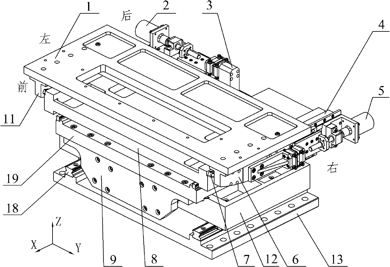
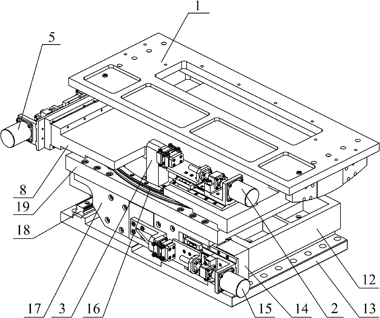
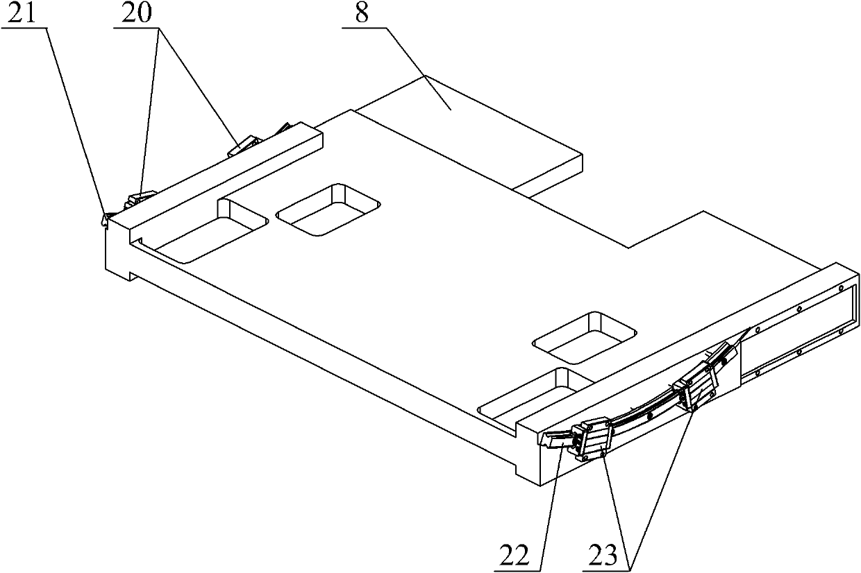
[0016] Specific implementation mode one: combine Figure 1 to Figure 6 Describe this embodiment. The high-precision pose adjustment device in this embodiment is composed of a pitch adjustment unit, a yaw adjustment unit, an in-plane adjustment unit, a straight line adjustment unit, and an adjustment base 13; the pitch adjustment unit is composed of a pitch adjustment plate 1, The pitch adjustment right guard plate 6, the pitch adjustment left guard plate 11, the pitch adjustment guide rail assembly 7, the pitch adjustment micro-driver 5 and the pitch adjustment connector 4 are composed, and the pitch adjustment guide rail assembly 7 is composed of a pitch adjustment left circular arc Guide rail 21, a section of pitch adjustment right circular arc guide rail 21, a pair of pitch adjustment left guide rail sliders 20 and a pair of pitch adjustment right guide rail sliders 23;
[0017] The yaw adjustment unit is composed of a yaw adjustment frame 8, a yaw adjustment micro-driver 2...
specific Embodiment approach 2
[0028] Specific implementation mode two: combination figure 1 , figure 2 , Figure 7 and Figure 8 Description, the pitch adjustment micro-driver 5 of the present embodiment is made up of pitch stepper motor 33, pitch motor base 34, pitch motor coupling 35, pitch bearing block 36, pitch ball screw 37, pitch screw nut 38, pitch reference plane Support plate 39, pitch micro-drive guide rail slider 49, pitch micro-drive linear guide 52, pitch adjustment locking backing plate 50, pitch adjustment locking plate 48, pitch column plane plate 40, pitch steel ball 41, pitch spring 47, pitch Steel ball seat 42, pitching steel ball supporting plate 46, pitching push plate 43, pitching adjustment connecting bent plate 44, pitching micro-drive base 51, four pitching first hanging spring screws 45 and four pitching second hanging spring screws 69 composition;
[0029] The output end of the pitching stepper motor 33 is connected to one end of the pitching ball screw 37 through the pitch...
specific Embodiment approach 3
[0030] Specific implementation mode three: combination figure 1 , figure 2 , Figure 9 and Figure 10 Explain that the yaw adjustment micro-driver 2 of the present embodiment is composed of a yaw stepper motor 70, a yaw motor base 71, a yaw motor coupling 72, a yaw bearing seat 73, a yaw ball screw 74, and a yaw wire. Bar nut 75, yaw reference plane support plate 76, yaw micro-drive guide rail slider 77, yaw micro-drive linear guide 78, yaw adjustment locking backing plate 79, yaw adjustment locking plate 80, yaw column flat Panel 81, yaw steel ball 82, yaw spring 83, yaw steel ball seat 84, yaw steel ball supporting plate 85, yaw push plate 86, yaw adjustment connecting bent plate 87, yaw micro-drive base 88 , four yaw first hanging spring screws 89 and four yaw second hanging spring screws 90;
[0031]The output end of the yaw stepping motor 70 is connected to one end of the yaw ball screw 74 through the yaw motor coupling 72. The yaw ball screw 74 is supported by the y...
PUM
 Abstract
Description
Claims
Application Information
 - R&D
- Intellectual Property
- Life Sciences
- Materials
- Tech Scout
- Unparalleled Data Quality
- Higher Quality Content
- 60% Fewer Hallucinations
Browse by: Latest US Patents, China's latest patents, Technical Efficacy Thesaurus, Application Domain, Technology Topic, Popular Technical Reports.
© 2025 PatSnap. All rights reserved.Legal|Privacy policy|Modern Slavery Act Transparency Statement|Sitemap|About US| Contact US: help@patsnap.com


