Check patentability & draft patents in minutes with Patsnap Eureka AI!

Sensor apparatus

A sensor device and sensor technology, applied in the direction of measuring devices, electrical devices, instruments, etc., can solve the problems of not fully considering the workability of circuit boards

Active Publication Date: 2012-07-18
NGK SPARK PLUG CO LTD
View PDF8 Cites 3 Cited by
  • Summary
  • Abstract
  • Description
  • Claims
  • Application Information

AI Technical Summary

Problems solved by technology

[0007] However, conventionally, sufficient consideration has not been given to the workability of housing the circuit board in the housing during the manufacturing process of the sensor device.

Method used


Image

  • Sensor apparatus
  • Sensor apparatus
  • Sensor apparatus

Examples


no. 1 example

[0042] A-1. Structure of sensor device

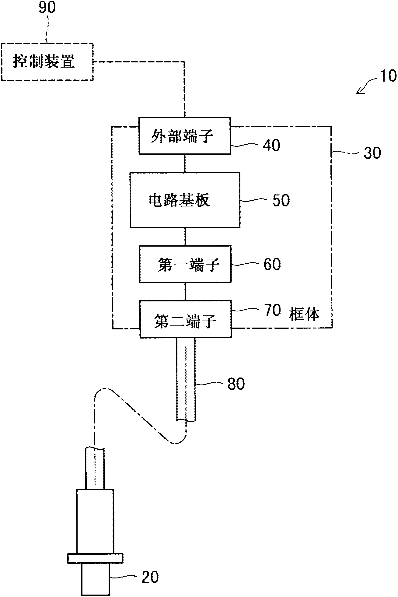
[0043] figure 1It is an explanatory diagram showing the structure of the sensor device 10 . The sensor device 10 includes a sensor 20 , a housing 30 , an external terminal 40 , a circuit board 50 , a first terminal 60 , a second terminal 70 , and a cable 80 . The sensor device 10 can be electrically connected to the control device 90 which is the outside of the sensor device 10 through the external terminal 40 , and outputs an electric signal based on the detection result of the sensor 20 to the control device 90 through the external terminal 40 . In this embodiment, the sensor 20 is an oxygen (O2) sensor installed on the exhaust pipe of the internal combustion engine to detect the oxygen concentration in the exhaust gas, and the control device 90 is a device for controlling the internal combustion engine based on the oxygen concentration in the exhaust gas.

[0044] The sensor 20 of the sensor device 10 is constituted by a known stru...

no. 2 example

[0080] B-1. Structure of sensor device

[0081] The schematic structure of the sensor device 10 in the second embodiment and figure 1 The first embodiment shown is the same. The sensor device 10 of the second embodiment includes, like the first embodiment, a sensor 20 , a housing 30 , an external terminal 40 , a circuit board 50 , a first terminal 60 , a second terminal 70 , and a cable 80 . In the description of the second embodiment, among the parts of the sensor device 10 in the second embodiment that have the same functions as those in the first embodiment, the same reference numerals as those in the first embodiment are used.

[0082] Figure 7 as well as Figure 8 It is a perspective view showing the detailed structure of the housing 30 in the second embodiment. exist Figure 7 The perspective view seen from the upper side of the frame body 30 is shown in Figure 8 A perspective view seen from the rear side of the housing 30 is shown in FIG. The housing 30 of the ...


PUM


Abstract

The invention provides a sensor apparautus to improve workability in a process of manufacturing a sensor apparatus. A housing (30) of a sensor apparatus (10) includes a first member (100) and a second member (200). The first member (100) supports a circuit board (50) in such a condition that the circuit board (50) is electrically connected to an external terminal (40). The second member (200) receives a cable (80) inserted thereinto and is engaged with the first member (100), thereby accommodating the circuit board (50) in cooperation with the first member (100). As a result of engagement between the first member (100) and the second member (200), the housing (30) establishes an electric connection of the circuit board (50) to the cable (80).

Description

technical field [0001] The present invention relates to a sensor device including a sensor, and more particularly to a sensor device in which a circuit board for driving the sensor is connected to the sensor via a cable. Background technique [0002] As a sensor device in which a circuit board is connected to a sensor via a cable, a device that detects the concentration of specific gas components such as oxygen and nitrogen oxides through a sensor and outputs an electrical signal from the circuit board to the outside according to the detection result (for example, refer to Patent Document 1 ~3). The circuit board of the sensor device is usually accommodated in a housing for the purpose of impact resistance, waterproofing, dustproofing, and the like, and is protected. [0003] prior art literature [0004] Patent Document 1: Japanese Patent Application Laid-Open No. 59-170723 [0005] Patent Document 2: Japanese Patent Laid-Open No. 2000-171435 [0006] Patent Document 3:...

Claims


Application Information

Patent Timeline
IPC IPC(8): G01N27/00
CPCG01N27/4062G01N27/409G01K7/023
Inventor 小林章弘吉田伸吾
Owner NGK SPARK PLUG CO LTD
Features
  • R&D
  • Intellectual Property
  • Life Sciences
  • Materials
  • Tech Scout
  • Unparalleled Data Quality
  • Higher Quality Content
  • 60% Fewer Hallucinations
Learn More