Receiver and image suppression method thereof

An image suppression and receiver technology, applied in electrical components, transmission systems, etc., can solve the problems of useful signal interference, phase and amplitude unbalanced signal images, influence spurs, etc., to achieve the effect of in-band spurs and sensitivity improvement

Active Publication Date: 2012-07-18
COMBA TELECOM SYST CHINA LTD
View PDF5 Cites 20 Cited by
  • Summary
  • Abstract
  • Description
  • Claims
  • Application Information

AI Technical Summary

Problems solved by technology

[0003] During the application of the zero-IF receiver, it was found that the phase and amplitude imbalance of the I-channel and Q-channel data lead to the existence of signal mirroring, which will affect the system indicators
When the main signal is symmetrical about the center frequency point, the mirror image and the main signal will overlap together, which will affect the error vector magnitude of the signal; when the main signal is not symmetrical about the center frequency point, the main signal and the mirror image are symmetrical about the center frequency point, affecting the system The in-band spurs will interfere with other useful signals in the band
The zero-IF modulator of the uplink of the zero-IF receiver has the image suppression function, but it can only suppress the image to about -40dbm, and the image at this time still affects the system index

Method used


Image

  • Receiver and image suppression method thereof
  • Receiver and image suppression method thereof
  • Receiver and image suppression method thereof

Examples


Embodiment Construction

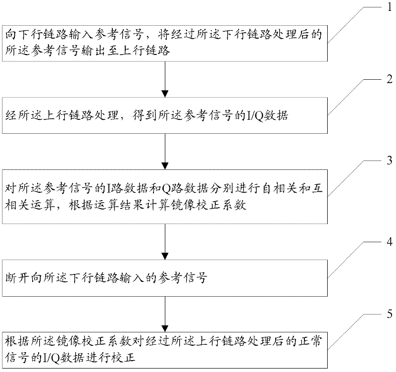
[0039] The image suppression method of the receiver in the embodiment of the present invention, such as figure 1 shown, including steps:

[0040] Step 1. Input a reference signal to the downlink, and output the reference signal processed by the downlink to the uplink;

[0041] Step 2. Obtain the I / Q data of the reference signal through the uplink processing;

[0042] Step 3, performing autocorrelation and cross-correlation calculations on the I-way data and Q-way data of the reference signal, and calculating the image correction coefficient according to the calculation results;

[0043] Step 4, disconnecting the reference signal input to the downlink;

[0044] Step 5. Correct the I / Q data of the normal signal after the uplink processing according to the image correction coefficient.

[0045] The reason for the mirror image is that the phase and amplitude of the I / Q data are unbalanced. Therefore, the root of image suppression is to balance the IQ data. During specific impl...


PUM


Abstract

The embodiment of the invention discloses a receiver and an image suppression method thereof; after the receiver is electrified, a reference signal is input into a down link; the reference signal is processed by the down link and then is processed by an up link, and in-phase/quadrature (I/Q) data is obtained; the autocorrelation, the cross-correlation, the summing and averaging and an image correction coefficient of the obtained I/Q data are sequentially calculated, and the image correction coefficient is obtained; and the reference signal is finally cut off. Consequently, when in normal communication, after a radio frequency signal is processed by the up link, an image can be corrected according to the image correction coefficient. The method is particularly applicable to a homodyne receiver; the reference signal is preferred to be a white noise signal; and after primary image correction of an uplink homodyne modulator, the radio frequency signal carries out secondary image correction according to the image correction coefficient. Finally, the image can be corrected to -70dbm, and the error vector amplitude, in-band stray, sensitivity and other indicators of a system are improved.

Description

technical field [0001] The invention relates to the technical field of wireless communication, in particular to a receiver and an image suppression method thereof. Background technique [0002] The receiver generally includes an uplink and a downlink, and the signal processed by the uplink usually exists. The zero-IF receiver has the advantages of small size, low cost, and easy single-chip integration, and has become a very competitive radio frequency receiver. A structure of , which has received extensive attention in the field of wireless communication. [0003] During the application process of the zero-IF receiver, it was found that the phase and amplitude imbalance of the I-channel and Q-channel data led to the existence of signal images, which would affect the system indicators. When the main signal is symmetrical about the center frequency point, the mirror image and the main signal will overlap together, which will affect the error vector magnitude of the signal; wh...

Claims


Application Information

Patent Timeline
Patent Type & Authority Applications(China)
IPC IPC(8): H04B1/16
Inventor 龚贺张嘉鹏
Owner COMBA TELECOM SYST CHINA LTD
Why Eureka
Try Eureka