Idle detection device of elevator drive

A detection device and drive device technology, which is applied in transportation, packaging, elevators, etc., can solve the problems of expensive rotating equipment, troubles in configuration space, and rising costs.

Inactive Publication Date: 2014-11-05
TOSHIBA ELEVATOR KK
View PDF1 Cites 0 Cited by
  • Summary
  • Abstract
  • Description
  • Claims
  • Application Information

AI Technical Summary

Problems solved by technology

There are technical problems that the rotating equipment becomes expensive by making the shaft rotate, and the space for installing the pulse generator needs to be secured
[0009] In addition, when position detection is performed by a detector having light emitting and receiving functions and a shield plate for blocking the light, it is necessary to arrange a U-shaped detector and a shield plate that enters the opening, The detector cannot be arranged at a position overlapping with the projection surface of the car, but it is necessary to secure an arrangement space
In this case, in order to avoid interference with other equipment of the elevator, it may be difficult to arrange space
In addition, several shielding plates are required for position detection, resulting in an increase in cost

Method used


Image

  • Idle detection device of elevator drive
  • Idle detection device of elevator drive
  • Idle detection device of elevator drive

Examples


no. 1 approach

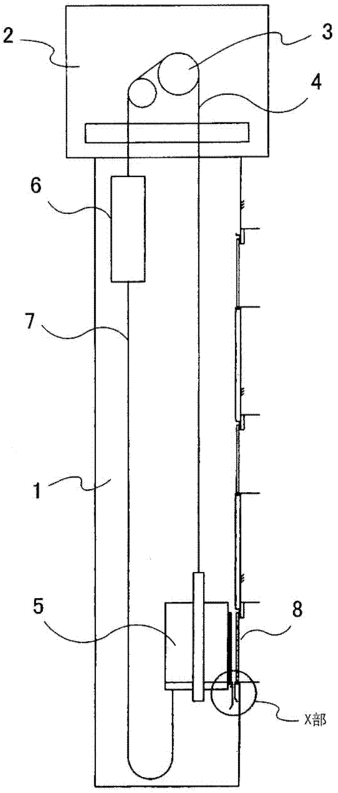
[0022] First, a general elevator to which the idling detection device of the elevator drive device is applied will be briefly described. figure 1 It is a figure which shows the whole structure of a general elevator. like figure 1 As shown, in the machine room 2 in the upper part of the hoistway 1 of an elevator, the hoisting machine (not shown) is installed. A car 5 is suspended from one end of a main rope 4 suspended from a drive sheave 3 of the hoisting machine. On the other hand, at the other end of the main rope 4, a counterweight 6 is suspended.

[0023] In order to eliminate the change in the mass of the main rope 4 due to the position of the car 5 , a compensation rope (or a compensation chain) 7 is attached to the lower sides of the car 5 and the counterweight 6 . On each floor, the car 5 and the hoistway 1 for getting in and out of passengers are opened, and a landing door 8 is provided.

[0024] figure 2 is as figure 1 A detailed view of part X of the car 5 an...

no. 2 approach

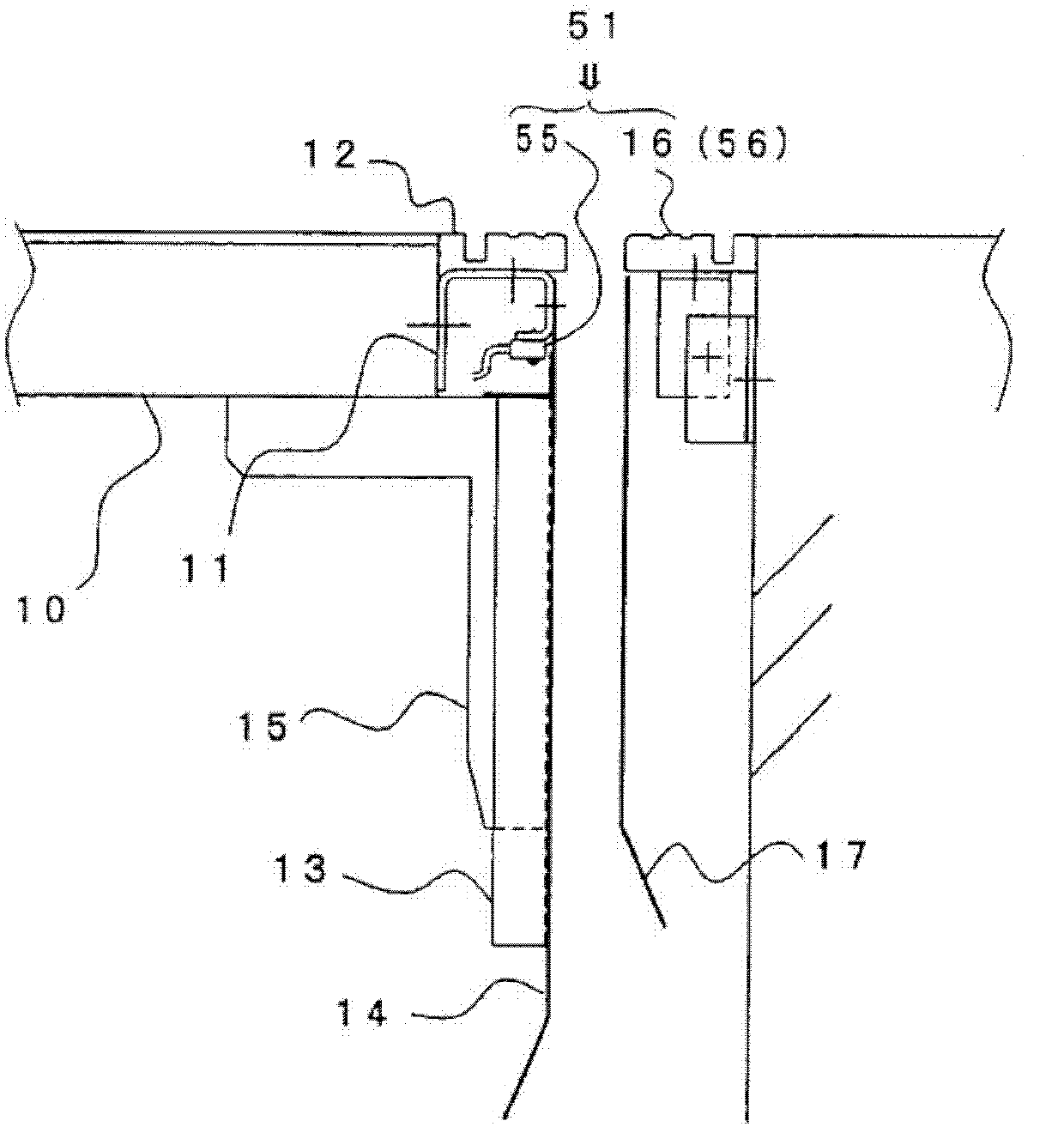
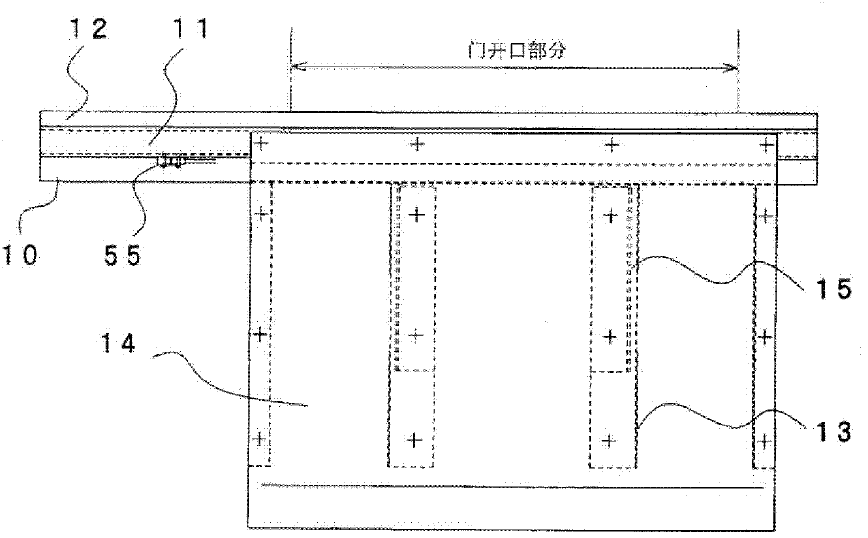
[0039] Next, the second embodiment will be described. FIG. 6( a ) is a plan view showing the second embodiment, and FIG. 6( b ) is a vertical cross-sectional view.

[0040] As in the first embodiment, when the hall-side door sill 16 is used as a reflection member for the object 56 to be detected, it is necessary to have an entrance and exit of the hall on each floor. On the other hand, in the case of a fast-moving zone type elevator having a passing floor, there are cases where there is no entrance and exit at each floor.

[0041]In the second embodiment, the detector 55 is arranged so as to face the car side on the front surface of the rail bracket 70 to which the guide rail 83 is fixed.

[0042] Generally, one or more rail brackets 70 are provided on each floor of an elevator. By equipping the detector 55 with the function of projecting and receiving light, the rail bracket 70 can be used as a reflection member as the object to be detected 56, and can function as a positio...

no. 3 approach

[0045] Next, the third embodiment will be described. FIG. 7( a ) is a plan view showing the third embodiment, and FIG. 7( b ) is a vertical cross-sectional view. In the third embodiment, the structure of the detector 55 in the first and second embodiments is changed. like Figure 4 As shown, in the front portions of the light-emitting portion 58 and the light-receiving portion 59 of the detector 55, the polarizing filters 60a and 60b that transmit only the light that vibrates in a certain direction are transmitted by the vibration of the respective transmitted light. The direction is set at right angles.


PUM


Abstract

The invention provides an idle detection device of an elevator drive, which can realize a position detection device used for detecting idle with low costs and little space. The device comprises a position detection device which is provided with a detector and an object to be detected, wherein the detector is provided with a signal transmitting part for transmitting signals and a signal receiving part for receiving signals and is used for detecting signals; the object to be detected enables the signals from the signal transmission part reflect and leads the signals to the signal receiving part; and a timer device used for detecting time. One of the detector and the object to be detected is configured to at a cage side of the elevator and the other is appositively configured to be at a well side of the elevator; the signal transmitting part and the signal receiving part are configured to be at a same side; the timer device is used for calculating detecting time in the position detection device; the calculated value and a predetermined time are compared to detect idle of the elevator drive.

Description

[0001] This application is based on Japanese Patent Application No. 2011-10606 (filing date: January 21, 2011), and enjoys the priority of this application. This application contains the entire contents of this application by reference to this application. technical field [0002] The present invention relates to an idling detection device of an elevator driving device. Background technique [0003] When the car or the counterweight cannot be moved for some reason, if the car or the counterweight is kept in the immovable state and the operation command is issued by the control device to continue the operation, the driving device (hoist) will be driven. Abnormal wear occurs between the sheave and the rope suspending the car, the abnormal wear progresses, and in the worst case, a dangerous state such as cutting of the rope may occur. [0004] For example, in the GB regulations which are the national standards of the People's Republic of China and the EN regulations in Europe,...

Claims


Application Information

Patent Timeline
Patent Type & Authority Patents(China)
IPC IPC(8): B66B5/02
Inventor 饭岛智树
Owner TOSHIBA ELEVATOR KK
Why Eureka
Try Eureka