Method of detecting an in-range failure of a brake pedal position sensor

A brake pedal and sensor technology, applied in the direction of brakes, brake action activation devices, brake components, etc.

Active Publication Date: 2015-02-25
GM GLOBAL TECH OPERATIONS LLC
View PDF5 Cites 0 Cited by
  • Summary
  • Abstract
  • Description
  • Claims
  • Application Information

AI Technical Summary

Problems solved by technology

However, this redundancy, a second redundant brake pedal position sensor, is not always available

Method used


Image

  • Method of detecting an in-range failure of a brake pedal position sensor
  • Method of detecting an in-range failure of a brake pedal position sensor
  • Method of detecting an in-range failure of a brake pedal position sensor

Examples


Embodiment Construction

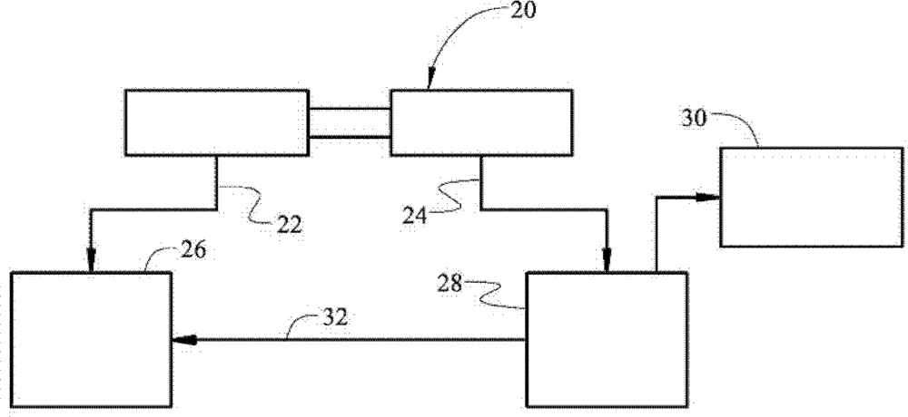
[0012] Reference is made to the drawings, wherein like reference numerals refer to like parts throughout the several views. The brake pedal position sensor is approximately figure 1 20 of them are shown. refer to figure 1 , the brake pedal position sensor 20 is configured to sense the position of a brake pedal (not shown) of a vehicle (not shown). The brake pedal position sensor 20 produces an electrical signal whose strength varies with the movement of the brake pedal. Accordingly, the signal from the brake pedal position sensor 20 varies with respect to changes in the position of the brake pedal.

[0013] The brake pedal position sensor 20 may include any brake pedal position sensor 20 capable of generating a first signal 22 and a second signal 24 , where each of the first signal 22 and the second signal 24 is indicative of the position of the brake pedal. The first signal 22 is directed to a controller 26 . Controller 26 may include, but is not limited to, an engine co...


PUM


Abstract

A method of detecting an in-range failure of a brake pedal position sensor includes calculating the difference between a minimum position and a maximum position of the brake pedal position sensor. The calculated difference is weighted to define a fast test weighted input value and / or a full test weighted input value. A cumulative test result value is incremented by the fast test weighted input value and / or the full test weighted input value. The cumulative test result value is filtered to define a moving average of the cumulative test result value after each incremented occurrence. The moving average of the cumulative test result value is tracked to determine if the brake pedal position sensor is functioning properly.

Description

technical field [0001] The present invention generally relates to detecting an in-range failure of a brake pedal position sensor. Background technique [0002] The brake pedal position sensor senses the position of the brake pedal and sends an electrical signal to the engine control module indicating the current position of the brake pedal. The electrical signal varies within the normal operating range with the position of the brake pedal. An electrical signal may be defined as operating within range when the electrical signal is within the normal operating range. [0003] The ECM includes an on-board diagnostic that continuously monitors the electrical signal from the brake pedal position sensor. When the electrical signal from the brake pedal position sensor is outside the normal operating range, ie out of range, the onboard diagnostics can easily determine that the brake pedal position sensor is not functioning properly. However, the electrical signal from the brake pe...

Claims


Application Information

Patent Timeline
Patent Type & Authority Patents(China)
IPC IPC(8): G01D18/00
CPCB60T17/22B60W2540/12G05G1/38B60T17/221B60T7/042
Inventor A.M.泽特尔J.F.范吉尔德A.A.阿特梅赫S.D.沙利文
Owner GM GLOBAL TECH OPERATIONS LLC
Why Eureka
Try Eureka