Touch screen with infrared rays transmitted inside screen body and method for identifying touch points

A touch screen and infrared technology is applied to the touch screen with infrared transmission inside the screen body and the field of identifying touch points to achieve the effects of improving stability, improving assembly, and improving aesthetics.

Active Publication Date: 2012-08-01
GENERALTOUCH TECH
View PDF7 Cites 17 Cited by
  • Summary
  • Abstract
  • Description
  • Claims
  • Application Information

AI Technical Summary

Problems solved by technology

[0007] The purpose of the present invention is to overcome the above-mentioned problems existing in the existing infrared touch screen, and provide a touch screen in which infrared rays are transmitted inside the screen body and a method for identifying touch points thereof. The present invention utilizes the principle of total reflection to transmit infrared light inside the touch screen body, Make the touch body must be close to the surface of the touch screen to generate a touch response, which solves the problem of the touch suspension height; and because the infrared light is transmitted inside the touch screen, the infrared emitting unit does not need to be placed on the surface of the touch screen, thereby realizing the wireless touch screen. frame

Method used


Image

  • Touch screen with infrared rays transmitted inside screen body and method for identifying touch points
  • Touch screen with infrared rays transmitted inside screen body and method for identifying touch points
  • Touch screen with infrared rays transmitted inside screen body and method for identifying touch points

Examples


Embodiment 1

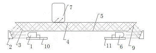
[0039] In this embodiment, reflectors are used to change the transmission direction of light, and the material of the touch screen body is glass. Such as figure 2As shown, when the infrared light emitted by the infrared emitting unit 1, that is, the infrared emitting tube, is reflected by the reflector 2, it will be perpendicular to the incident surface 3 of the touch screen body and enter the touch screen body. If the angle is greater than the critical angle of total reflection (the critical angle of light incident from the glass material to the air is 41.8), the infrared light transmitted inside the touch screen body can form a total reflective surface between the upper reflective surface 4 and the lower reflective surface 5 of the touch screen body. Reflection, the light will not be transmitted to the outside of the touch screen body but is transmitted inside the touch screen body, but emitted from the other side of the touch screen body, reflected by the mirror 2 and then...

Embodiment 2

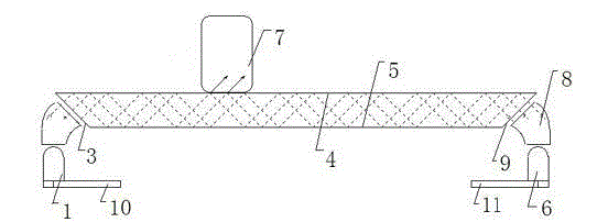
[0042] Use the light guide rod to change the transmission direction of light. Such as image 3 As shown, when the infrared light emitted by the infrared emitting unit 1 changes the transmission direction of the light through the light guide column 8, it will be perpendicular to the incident surface 3 and enter the touch screen body, as long as the incident angle of the light on the reflective surface 4 on the touch screen body is greater than the full The critical angle of reflection (the critical angle of light incident from the glass material to the air is 41.8·), the infrared light transmitted inside the touch screen body can form total reflection on the inner surface of the touch screen body, and the light will not be transmitted to the outside of the touch screen body but It is transmitted inside the touch screen body and emitted from the other side of the touch screen body. After changing the transmission direction of the light through the light guide column 8, it enters...

Embodiment 3

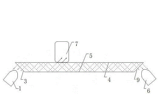
[0045] A touch screen in which infrared rays are transmitted inside the screen body. The infrared light emitted by the infrared emitting unit 1 enters the touch screen body, forms total reflection on the upper reflective surface 4 and lower reflective surface 5 inside the touch screen body, and transmits to the infrared receiving unit 6 .

[0046] In the present invention, the incident surface 3 and the outgoing surface 9 are formed around the touch screen body between the upper reflective surface 4 and the lower reflective surface 5, that is, when the incident surface is formed on one side of the touch screen body, the corresponding other The side forms the exit surface.

[0047] The angle between the incident surface 3 and the upper reflective surface 4 depends on the refractive index of the light-transmitting material, as long as the light passing through the incident surface passes through the light-transmitting material, it can be totally reflected on the upper reflecting ...


PUM


Abstract

The invention discloses a touch screen with infrared rays transmitted inside a screen body and a method for identifying touch points. In the touch screen, the infrared rays sent out by an infra-red emission unit ripe into the touch screen body, are totally reflected by an upper reflecting surface and a lower reflecting surface inside the touch screen body, and are transmitted into the infrared receiving unit. According to the invention, the infrared rays are transmitted inside the touch screen body by using the total reflection principle, and a touch body is enabled to be clung to the surface of the touch screen to generate touch response, so that the problem of touch floating height is solved; and since the infrared rays are transmitted inside the touch screen, the infra-red emission unit is not required to be placed on the surface of the touch screen. Therefore, an edge frame free touch screen is realized.

Description

technical field [0001] The invention relates to an infrared touch screen, in particular to a touch screen in which infrared rays are transmitted inside the screen body and a method for identifying touch points thereof. Background technique [0002] The existing infrared touch system adopts the infrared emission tubes and infrared receiving tubes arranged uniformly in the X and Y directions along the touch area, and the control and driving circuit drives the infrared emission under the control of the MCU execution code. The tube and the infrared receiving tube are scanned correspondingly to form an infrared matrix that crosses horizontally and vertically in the X direction and the Y direction. When there is a touch, fingers or other objects will block the horizontal and vertical infrared rays passing through the point, and the control system can judge the position of the touch point on the touch screen. [0003] At present, in the field of infrared touch screen, such as the ...

Claims


Application Information

Patent Timeline
Patent Type & Authority Applications(China)
IPC IPC(8): G06F3/042
Inventor 蒲彩林
Owner GENERALTOUCH TECH
Why Eureka
Try Eureka