Pulse modulation control method and device for driving LED

A technology of LED driving and pulse modulation, which is applied in the direction of lighting devices, lamp circuit layout, light sources, etc., can solve the problems of flickering and uneven luminous brightness of LED lighting devices, and achieve the solution of flickering and uneven luminous brightness, smooth change and uneven brightness uniform effect

Active Publication Date: 2012-08-01
SHENZHEN SUNMOON MICROELECTRONICS
View PDF4 Cites 14 Cited by
  • Summary
  • Abstract
  • Description
  • Claims
  • Application Information

AI Technical Summary

Problems solved by technology

[0004] The purpose of the present invention is to provide a pulse modulation control method for LED driving, which aims to solve the problems of flickering and uneven luminance of the LED light-emitting device in the operation of the pulse modulation method provided by the prior art

Method used


Image

  • Pulse modulation control method and device for driving LED
  • Pulse modulation control method and device for driving LED
  • Pulse modulation control method and device for driving LED

Examples


Embodiment 1

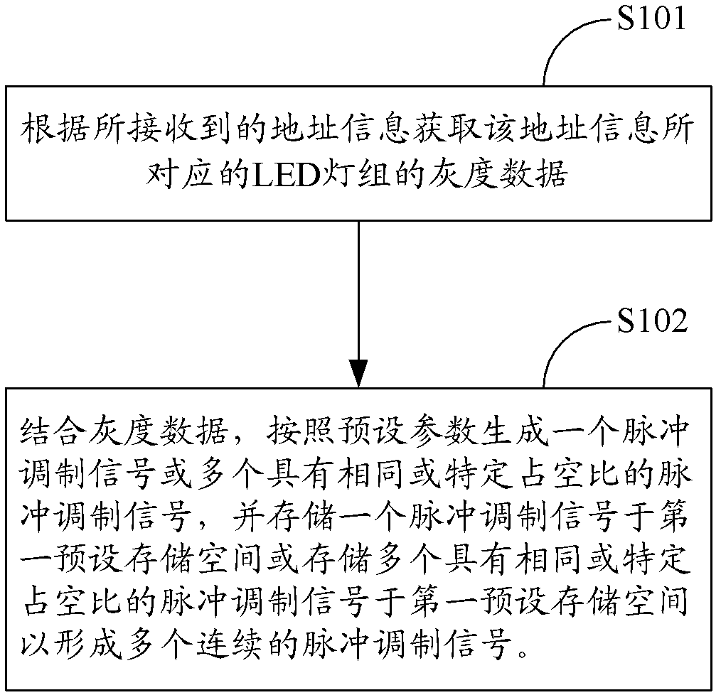
[0034] image 3 The implementation flow of the pulse modulation control method for LED driving provided by the first embodiment of the present invention is shown. For the convenience of description, only the parts related to the first embodiment of the present invention are shown, and the details are as follows:

[0035] In step S101, according to the received address information, the grayscale data of the LED lamp group corresponding to the address information is obtained.

[0036] Among them, the address information is corresponding to each LED light group, that is, each LED light group is assigned with specific address information, which can make the grayscale data in the data packet and the LED light group with specific address information form one by one corresponding relationship.

[0037] In step S102, combined with the grayscale data, a pulse modulation signal or multiple pulse modulation signals with the same or specific duty cycle are generated according to preset p...

Embodiment 2

[0039] Figure 4 The specific implementation process of the pulse modulation control method for LED driving provided by the second embodiment of the present invention is shown. For the convenience of description, only the parts related to the second embodiment of the present invention are shown, and the details are as follows:

[0040] In this embodiment, step S201 is the same as step S101 in the first embodiment of the present invention, and steps S201 to S208 mentioned in this embodiment are included in step S102 in the first embodiment of the present invention.

[0041] In step S201, according to the received address information, the grayscale data of the LED lamp group corresponding to the address information is obtained.

[0042] In step S202, set the binary counting upper limit of the input basic clock signal according to the number of digits of the grayscale data; step S202 is specifically:

[0043] Set the digits of the binary count value according to the digits of th...

Embodiment 3

[0077] Figure 6 The specific implementation process of the pulse modulation control method for LED driving provided by the third embodiment of the present invention is shown. For the convenience of description, only the parts related to the third embodiment of the present invention are shown, and the details are as follows:

[0078] In step S301, according to the received address information, the grayscale data of the LED lamp group corresponding to the address information is obtained.

[0079] In step S302, a PWM pulse modulation signal is generated according to the gray scale data.

[0080] In step S303, the PWM pulse modulation signal is divided into a plurality of pulse modulation signals with a specific duty cycle in combination with grayscale data; step S303 is specifically:

[0081] A cycle corresponding to the PWM pulse modulation signal is divided into a plurality of first sub-cycles and a second sub-cycle according to formula (3):

[0082] T=(2 m -1)*2 h *2 f-m...


PUM


Abstract

The invention is suitable for the field of driving of a LED and provides a pulse modulation control method and a pulse modulation control device for driving the LED. In the invention, according to received address information, gray level data of an LED lamp bank corresponding to the address information is acquired; then a pulse modulation signal or a plurality of pulse modulation signals with the same or special duty ratio are generated in a pulse modulation period according to preset parameters by combining the gray level data; and one pulse modulation signal is stored in a first preset storage space or a plurality of pulse modulation signals with the same or special duty ratio are stored in the first preset storage space to form a plurality of continuous pulse modulation signals with periodicity, so that the brightness of the LED in the working process is ensured to be changed smoothly without the phenomenon of blink or nonuniform brightness, and thus, the problems of blink and nonuniform brightness when the LED light-emitting device works, which are caused by a pulse modulation mode provided in the prior art, are solved.

Description

technical field [0001] The invention belongs to the field of LED driving, and in particular relates to a pulse modulation control method and device for LED driving. Background technique [0002] In recent years, LED, as a basic light-emitting device of various light-emitting devices, has been widely used in various lighting equipment. For example, red, green and blue LED lights are assembled into light groups, and then the light groups are connected in series or in parallel to form LED light strips, which are used for decorative lighting, guardrail lights, and indoor and outdoor video walls. In the past, the driver chips of multiple LED lamp groups were connected in series with the main control device (such as figure 1 shown), and uses pulse width modulation (Pulse Width Modulation, PWM) as the pulse modulation method to drive and control the LED light strip. However, in the above control method, each level of LED light group needs The driver chip of the group obtains the ...

Claims


Application Information

Patent Timeline
Patent Type & Authority Applications(China)
IPC IPC(8): H05B37/02
Inventor 李照华石磊符传汇陈克勇胡富斌杨亚吉
Owner SHENZHEN SUNMOON MICROELECTRONICS
Why Eureka
Try Eureka