Hydraulic damper spool valve

A technology of hydraulic damping and hydraulic damper, which is applied in the valve field of hydraulic damper, can solve problems such as difficult mathematical technology, complexity and cost constraints, and restrictions, and achieve the effect of reducing complexity

Active Publication Date: 2014-12-24
摩缇马帝有限公司
View PDF12 Cites 0 Cited by
  • Summary
  • Abstract
  • Description
  • Claims
  • Application Information

AI Technical Summary

Problems solved by technology

Another disadvantage of the compliant plate device is that due to the complex operating mechanism of the pressure-flow characteristic, it cannot be easily predicted using mathematical techniques
Another disadvantage of this construction is that the pressure-flow characteristic tends to lose its original shape over time as the compliant plate material fatigues and loses its hardness and strength as well as small particles from seal, piston and shaft wear curves, becomes restricted between these compliant boards
While piezoelectric materials based on Jones' variable orifice valves can overcome the tolerance limitations of passive dampers, the associated complexity and cost are limiting
Furthermore, the '745 patent does not describe a device in which the pressure-flow characteristics can be predicted simply mathematically

Method used


Image

  • Hydraulic damper spool valve
  • Hydraulic damper spool valve
  • Hydraulic damper spool valve

Examples


Embodiment Construction

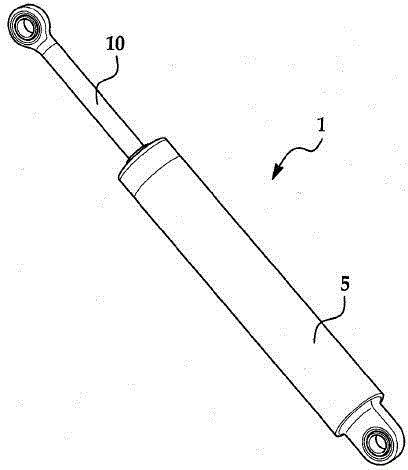
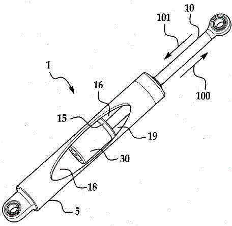
[0031] refer to figure 1 , figure 2 and Figure 4 , the hydraulic damper assembly (1) comprises: a main body (5), a shaft assembly (10) and a main piston (15) configured to divide the inner chamber of said main body (5) into an upper portion (16) and lower part (18). The upper (16) and lower (18) portions of the hydraulic damper contain hydraulic fluid (19). In a particular embodiment of the invention, a valve body (30) is mounted to the main piston (15) of said hydraulic damper. The valve body (30) may be mounted to the main piston (15) by mechanical fasteners or similar means. Such as figure 1 , figure 2 and Figure 4 As shown in the non-limiting embodiment shown, one or more seals (80) may be provided between the valve body (30) and the main piston (15). Also, said shaft assembly (10) may be threaded so that the shaft assembly can be engaged with the main piston (15) and valve body (30), as Figure 4 Non-limiting example shown.

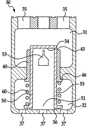
[0032] refer to image 3 and ...


PUM


Abstract

A hydraulic valve includes a main body, a valve body, a piston, a valve sleeve, a spool and a resilient energy storage member. The valve body and the piston are disposed within the main body. The valve body defines a first chamber, a second chamber, and a cylindrical passage connecting the first chamber and the second chamber. The valve sleeve is moveably disposed in the cylindrical passage. The spool is moveably disposed within the bore of the valve sleeve. The resilient energy storage member may be disposed between the valve sleeve and valve spool. The resilient energy storage member is compressed as pressure is induced in one of the first chamber or the second chamber such that the valve sleeve and the spool move relative to one another so that at least a portion of the shaped aperture is exposed to the first chamber or second chamber to allow a proportional amount of hydraulic fluid to flow between the first chamber and the second chamber.

Description

technical field [0001] The invention relates to a valve for a hydraulic damper, in particular a valve for a hydraulic damper of a wheeled vehicle suspension. Background technique [0002] Hydraulic dampers used to control dynamic systems employ a piston adapted to be slidably carried within the cylinder body, and a circumferential seal against the cylinder wall. The piston is configured to be attachable to the shaft assembly. The piston divides the cylinder body into two parts (upper and lower) that are connected by restrictive passages that block the connection between the upper and lower parts of the cylinder body when the shaft assembly moves relative to the cylinder body. Fluid flow rate between lower sections. In this way, the operating characteristics of the damper are defined by the relationship between pressure and flow, which may be dictated by the geometry of the restrictive passage between the upper and lower portions of the cylinder body. [0003] If these res...

Claims


Application Information

Patent Timeline
Patent Type & Authority Patents(China)
IPC IPC(8): F16F9/512
CPCF16F9/512
Inventor 劳伦斯·霍尔特彼得·屯斯塞尔迈克尔·格里克斯杰弗里·莱德曼
Owner 摩缇马帝有限公司
Why Eureka
Try Eureka